|
|
1. Introduction
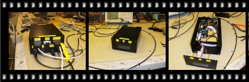
On our Ocean Bottom Seismograph (OBS) surveys we need to time tag airgun shot events with millisecond accuracy, in order to syncronize the seismic source to the clocks in the recording units positioned along the profiling line on the seabed. In the past, we have used the Ashtech GG24 GPS for time-tagging purposes, without any backup unit, which has seen us grow increasingly uncomfortable. Even if the Ashtech GG24 has performed flawlessly, there is no need to push our luck ... For the RV "Maria S. Merian" survey starting in January 2007 we decided to allocate a week to design, build and test a new time tagging unit, as a spare to the Ashtech GG24 GPS.
2. SpecificationsThe new unit has these specifications:
Data output formatThe RS-232 output data format will deviate slightly from the Ashtech GG24 format. The differences are highlighted below.
To summarize data format differences:
3. System description
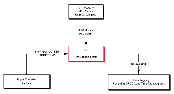
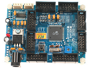
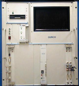
Fig. 3.1. System overview - time tagging Airgun Controller events. The TTU is based on a CPU board from www.futurlec.com - the AVR AtMega128 microcontroller (USD 28.90).
Board highlights:
The Garmin GPS35 is connected to the TTU through a 9-pin DSUB that also provides power (12 Vdc). The Pulse-per-second signal is routed via a coax cable. The Garmin GPS must be set to only transmit the $GPGGA NMEA telegram. RS232 parameters are 9600, 8, N, 1. Documentation on this GPS is here.
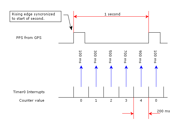
The GUNCO rear panel has a BNC output labeled "FTB Scope" (FTB = "Field Time Break"). The signal on this BNC is TTL level, active low pulse of 10 ms duration, where falling edge indicates nominal firing moment of the airguns. Connect the "FTB Scope" to Time Tagging Unit input marked "GUNCO FTB Scope" with a coax cable. 4. SoftwareTo achieve event time tag interpolation we need to divide each second into several time slots. We keep track of the current time slot sequence number. When an external event occurs, we record the time slot number and use this value to calculate the event time as fraction of the current second. The concept is illustrated in fig. 4.1. To simplify, each second is here subdivided into 5 parts.
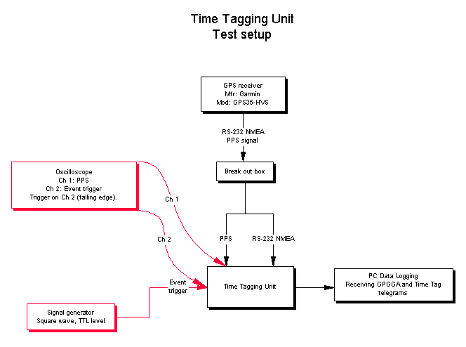
Fig. 4.1. Subdividing each second into time slices. In fig. 4.1, each time slot is 200 ms wide. We make the convention that events occuring within the first slot - where the counter value is 0 - should have a time stamp fraction of 100 ms, half the slot width. The pattern continues throughout the second, where events that takes place in the second slot will get a fractional value of 300 ms, and so forth. Generally, if we let N denote number of slots in a second, K the counter value recorded when an event occured and T the event's fractional time, we then have the expression: T = 1/(2N) + K*1/N Computing the event's fractional part (of a second) solves the first of the two problems associated with interpolation. The second problem is to tie this fraction to the complete time information transmitted in the $GPGGA telegram from the GPS. There is an added layer of complexity in that the telegram trails the PPS edge by a variable number of milliseconds. The first RS-232 character of the telegram can start from 100 to 600 milliseconds after the PPS leading edge that marks start of a second. So we need to establish an internal hour-minute-seconds variable that is updated at every PPS interrupt, so that at any moment in the remaining duration of the second, an external event interrupt can read and copy this internal time counter. The number of time slots must of course be much larger then five to achive the resolution that is needed. In our case we generate a Timer0 interrupt every 128 µsecond, yielding about 7813 time slots. This method is often implemented in ASICs to achieve time tagging with nanosecond resolution. 5. System testConfidence in the time tagging ability of the system depends on it being subjected to - and passing - thorough test procedures. Our Ashtech GG24 has already been shipped to RV "Maria Merian", so we cannot simply run the two time tagging units in parallell and compare results. However, two tests are designed that will examine system performance in detail. In both cases the test setup is as shown in fig 5.1.
Fig. 5.1. Test setup. Test no. 1In test no. 1, setup signal generator to square wave, 50% D.C., TTL level, 4.0 s period. Provided the signal generator oscillator is calibrated, the oscilloscope shows two traces that do not move relative to each other. Then increase the oscillator period so that the time stamp will seem to "loose" one or two milliseconds for each trigger. Perform this test until complete roll-over of the time stamp. E.g., you can have this sequence of TTT telegrams (milliseconds are highlighted): $GPGGA,112846,6023.0668,N,00519.7743,E,1,04,3.3,43.8,M,43.9,M,,*7A $PUIBR,TTT,,11:28:46.0044,34,7812*00 $GPGGA,112847,6023.0669,N,00519.7739,E,1,04,3.3,43.3,M,43.9,M,,*7C $GPGGA,112848,6023.0670,N,00519.7734,E,1,04,3.3,42.9,M,43.9,M,,*7D $GPGGA,112849,6023.0671,N,00519.7731,E,1,04,3.3,42.6,M,43.9,M,,*77 $GPGGA,112850,6023.0672,N,00519.7728,E,1,04,3.3,42.4,M,43.9,M,,*76 $PUIBR,TTT,,11:28:50.0029,22,7812*00 $GPGGA,112851,6023.0673,N,00519.7723,E,1,04,3.3,42.2,M,43.9,M,,*7B $GPGGA,112852,6023.0673,N,00519.7720,E,1,04,3.3,42.1,M,43.9,M,,*78 $GPGGA,112853,6023.0674,N,00519.7717,E,1,04,3.3,42.1,M,43.9,M,,*7A $GPGGA,112854,6023.0674,N,00519.7714,E,1,04,3.3,42.1,M,43.9,M,,*7E $PUIBR,TTT,,11:28:54.0012,9,7812*00 $GPGGA,112855,6023.0675,N,00519.7710,E,1,04,3.3,42.1,M,43.9,M,,*7A $GPGGA,112856,6023.0675,N,00519.7708,E,1,04,3.4,42.1,M,43.9,M,,*77 $GPGGA,112857,6023.0675,N,00519.7706,E,1,04,3.4,42.0,M,43.9,M,,*79 $GPGGA,112858,6023.0675,N,00519.7703,E,1,04,3.4,42.0,M,43.9,M,,*73 $PUIBR,TTT,,11:28:57.9997,7809,7812*00 $GPGGA,112859,6023.0675,N,00519.7700,E,1,04,3.4,42.0,M,43.9,M,,*71 $GPGGA,112900,6023.0675,N,00519.7698,E,1,04,3.4,42.0,M,43.9,M,,*7C $GPGGA,112901,6023.0675,N,00519.7696,E,1,04,3.4,42.0,M,43.9,M,,*73 $GPGGA,112902,6023.0675,N,00519.7693,E,1,04,3.4,42.1,M,43.9,M,,*74 $PUIBR,TTT,,11:29:01.9981,7797,7812*00 $GPGGA,112903,6023.0676,N,00519.7690,E,1,04,3.4,42.1,M,43.9,M,,*75 Notice the gradually decreasing millisecond values - 4.4, 2.9, 1.2, 999.7, 998.1. Exercise this test until the millisecond part returns to its initial value. Extract all timestamp telegrams from file and ensure timestamps change with a nearly constant value. Observe (highlighted in green) what happens when the second bounday is crossed. Time in the $GPGGA telegram is 112858, while time in the TTT is 11:28:57.9997. The reason is that the TTT is transmitted right after the $GPGGA telegram. Test no. 2Whereas test no 1 ensures that measurements are stable relative to each other, test no. 2 will confirm that absolute time is correct. Again setup signal generator to square wave, 50% D.C., TTL level, 4.0 s period. Change period untill falling edge of trigger signal is approx 2 milliseconds after PPS leading edge, i.e . event trigger occurs 2 milliseconds after start of new second. Increase oscilloscope time resolution and measure time difference with the cursors (assuming you have a digital scope). Compare time difference with millisecond value in TTT telegram. They should differ by not more than 200 µseconds. Example below, with millisecond value highlighted in yellow. $GPGGA,115610,6023.0673,N,00519.7681,E,1,04,3.4,24.4,M,43.9,M,,*7F $PUIBR,TTT,,11:56:10.0022,17,7812*00 $GPGGA,115611,6023.0673,N,00519.7683,E,1,04,3.4,24.4,M,43.9,M,,*7C $GPGGA,115612,6023.0672,N,00519.7686,E,1,04,3.4,24.6,M,43.9,M,,*79 $GPGGA,115613,6023.0671,N,00519.7690,E,1,04,3.4,24.7,M,43.9,M,,*7D $GPGGA,115614,6023.0670,N,00519.7694,E,1,04,3.4,25.0,M,43.9,M,,*79 $PUIBR,TTT,,11:56:14.0022,17,7812*00 Now reduce oscillator period slightly so that the millisecond value decreases slowly. The aim is to let the trigger event traverse the second boundary. $GPGGA,123110,6023.0551,N,00519.8133,E,1,04,3.9,39.4,M,43.9,M,,*7E $PUIBR,TTT,,12:31:09.9999,7811,7812*00 $GPGGA,123111,6023.0551,N,00519.8133,E,1,03,3.9,39.4,M,43.9,M,,*78 $GPGGA,123112,6023.0551,N,00519.8132,E,1,03,3.9,39.4,M,43.9,M,,*7A $GPGGA,123113,6023.0563,N,00519.8088,E,1,00,4.4,39.4,M,43.9,M,,*73 $GPGGA,123114,6023.0563,N,00519.8087,E,1,03,4.4,39.4,M,43.9,M,,*78 $PUIBR,TTT,,12:31:13.9999,7811,7812*00 $GPGGA,123115,6023.0563,N,00519.8087,E,1,03,4.4,39.4,M,43.9,M,,*79 $GPGGA,123116,6023.0563,N,00519.8086,E,1,03,4.4,39.4,M,43.9,M,,*7B $GPGGA,123117,6023.0574,N,00519.8037,E,1,03,4.9,39.4,M,43.9,M,,*7B $GPGGA,123118,6023.0574,N,00519.8036,E,1,03,4.9,39.4,M,43.9,M,,*75 $PUIBR,TTT,,12:31:18.0001,0,7812*00 $GPGGA,123119,6023.0583,N,00519.7987,E,1,03,5.3,39.4,M,43.9,M,,*7B $GPGGA,123120,6023.0590,N,00519.7942,E,1,03,5.7,39.4,M,43.9,M,,*7E $GPGGA,123121,6023.0596,N,00519.7901,E,1,03,6.1,39.4,M,43.9,M,,*7B $GPGGA,123122,6023.0602,N,00519.7868,E,1,03,6.4,39.4,M,43.9,M,,*7D $PUIBR,TTT,,12:31:22.0001,0,7812*00 Milliseconds (in yellow) can be seen to change from 999.9 to 0.1. The number highlighted in green is the value of the Timer0 interrupt counter at the moment the event trigger occured. The number in blue is the maximum value of the same counter before is was reset by start of new second, incremented by one, so it indicates the number of timeslices. So 7811 was the largest possible value of the counter (meaning the event trigger happened just before start of a new second). A Timer0 counter value of zero means the event trigger happened just after start of a new second. We will later compare the TTU with the Ashtech GG24 by operating the two systems in parallell, from the same event trigger source. 6. To-do list
7. Program listingThis unit was designed, built, tested and documented in about one week. The short time span available dictated our choice of hardware and software components. In particular, the AVR-BASCOM Basic compiler is really great to work with. The program amounts to more then 4kB machine code - which is the upper limit of the demo version of the AVR-BASCOM Basic compiler. So the full compiler version must be purchased (EUR 79). |
    1 '===============================================================================================
    2 '
    3 '                         T i m e   T a g g i n g   U n i t
    4 '                         - - - -   - - - - - - -   - - - -
    5 '
    6 '
    7 '          GPS based, the unit time stamps events with sub-millisec accuracy.
    8 '
    9 '                        http://www2.geo.uib.no/Maria_Merian/
   10 '
   11 '                             Dept. of Earth Science
   12 '                          University of Bergen, Norway
   13 '
   14 '
   15 ' This is a back-up for Ashtech GG24, a GPS receiver furnished with time tagging.
   16 ' It is meant to time stamp events from seismic airgun controller ("GUNCO").
   17 '
   18 ' GPS:
   19 '      Mod. : GPS35-HVS
   20 '      Mfr. : Garmin [www.garmin.com]
   21 '      COM  : NMEA telegrams output
   22 '             9600, 8, N, 1
   23 '      NMEA : Only $GPGGA should be selected
   24 '      PPS  : Routed to INT4 on MCU
   25 '
   26 ' External event:
   27 '      Type : TTL negative pulse (or closure), min 100 usec
   28 '             Input is NOT isolated by e.g. opto coupler.
   29 '             Falling edge is time tagged.
   30 '             Normally connected to Airgun Controller (GUNCO) "FTB Scope" output.
   31 '             Routed to INT5 on MCU
   32 '
   33 ' Indicator LEDs:
   34 '      #1   : RED. Lit during parsing of received GPS NMEA telegram.
   35 '      #2   : RED. State toggled during processing of GPS PPS interrupt.
   36 '             It thus appears to have 0.5 Hz frequency.
   37 '      #3   : GREEN/BLUE. Lit during processing of external event.
   38 '
   39 ' MCU board:
   40 '      Mod. : AVR AtMega128
   41 '      Mfr. : Futurlec [www.futurlec.com]
   42 '      MCU  : Atmel AtMega128
   43 '      Freq : 16 MHz
   44 '      COM1 : Input data from GPS, NMEA telegrams (only $GPGGA)
   45 '      COM2 : Output data to logging PC
   46 '             a) Event time stamps.
   47 '             b) Copy of input data telegrams.
   48 '      INT4 : PPS from GPS
   49 '      INT5 : Externalk event for time tagging.
   50 '
   51 ' Compiler:
   52 '      Mod. : BASCOM-AVR
   53 '      Mfr. : MCS Electronics [www.mcselec.com]
   54 '      Note : Demo version is limited to 4 kB code. Program exceeds this limit.
   55 '             Purchase and download compiler online (EUR 79.00)
   56 '
   57 '
   58 ' ------------------------------------------------------------------
   59 ' Rev  Date         By         Description
   60 ' ------------------------------------------------------------------
   61 ' 0.1  30 Dec 2006  O. Meyer   Initial version
   62 '
   63 '================================================================================================
   64
   65
   66 $regfile = "m128def.dat"                                    ' AtMega128
   67 $crystal = 16000000                                         ' XTAL = 16 MHz
   68 $baud = 9600                                                ' COM1 = 9600 bits/s
   69 $baud1 = 9600                                               ' COM2 = 9600 bits/s
   70 Config Portc = Output                                       ' PortC -> LEDs, active high
   71 Portc = 0
   72
   73 $hwstack = 32                                               ' Default use 32 for the hardware stack
   74 $swstack = 10                                               ' Default use 10 for the SW stack
   75 $framesize = 40                                             ' Default use 40 for the frame space
   76
   77 Open "com2:" For Binary As #1
   78
   79 'Configure LCD Screen. Connect LCD Module to ET-CLCD PORT
   80 Config Lcdbus = 4                                           ' 4-bit Mode
   81 Config Lcd = 16 * 2                                         ' 16x2 LCD display
   82 Config Lcdpin = Pin , Db4 = Portg.0 , Db5 = Portg.1 , Db6 = Portg.2 , Db7 = Portg.3 , E = Portd.7 , Rs = Portg.4
   83
   84
   85 '---------------------------------------------------------------
   86 '      C o n s t a n t s
   87 '---------------------------------------------------------------
   88
   89 Const True = 1
   90 Const False = 0
   91
   92
   93 '---------------------------------------------------------------
   94 '      D e c l a r e   v a r i a b l e s
   95 '---------------------------------------------------------------
   96
   97 Dim A As Byte                                               ' Used during reception of GPS NMEA telegram characters
   98 Dim Lcd_txt As String * 30                                  ' Text to LCD
   99 Dim Event_txt As String * 30                                ' Written to LCD when event occurs
  100 Dim Com2_txt As String * 100
  101
  102 Dim Char As String * 1                                      ' Serial input character from GPS
  103 Dim Nmea As String * 100                                    ' Holds complete NMEA telegram from GPS
  104 Dim S(20) As String * 25                                    ' Array of strings; for parsing of NMEA telegram
  105 Dim No_of_elements As Byte                                  ' Number of elements in NMEA telegram
  106
  107 '--- These are variables related to time keeping
  108 Dim Hours As String * 3 , Minutes As String * 3 , Seconds As String * 3
  109 Dim B_hours As Byte , B_minutes As Byte , B_seconds As Byte
  110 Dim Event_hours_str As String * 5 , Event_minutes_str As String * 5 , Event_seconds_str As String * 5
  111 Dim Event_hours As Byte , Event_minutes As Byte , Event_seconds As Byte
  112 Dim Event_happened As Byte                                  ' Flag set when event occurs, and acted upon in main loop
  113 Dim Sec_fraction As Single                                  ' Event time as fraction of second, in 0.1 milliseconds
  114
  115 Dim Pps_counter As Byte                                     ' GPS Pulse-per-second counter
  116 Dim Timer0_counter As Word                                  ' Incremented every Timer0 interrupt
  117 Dim Timer0_value As Word                                    ' Value of 'Timer0_value' when event occured
  118 Dim Event_value As Word                                     ' Some scratch pad variables
  119 Dim Long_tmp1 As Long
  120 Dim Long_tmp2 As Long
  121 Dim String_tmp As String * 20
  122
  123
  124 '-----------------------------------------------------------------------
  125 '      I n i t i a l i z e   v a r i a b l e s   a n d   L C D
  126 '-----------------------------------------------------------------------
  127
  128 Pps_counter = 0
  129 Timer0_counter = 0
  130 Timer0_value = 0
  131
  132 Event_value = 0
  133
  134 Event_hours = 0
  135 Event_minutes = 0
  136 Event_seconds = 0
  137 Event_happened = False
  138
  139 Event_txt = ""
  140
  141
  142 '----  LCD greeting
  143 Cls
  144 Cursor Off
  145 Lcd "GPS time tagging"
  146 Lowerline
  147 Lcd "IFG - UiB, 2006"
  148 Wait 3
  149
  150 Cls
  151 Lcd "Version 0.1"
  152 Lowerline
  153 Lcd "20 Dec 2006"
  154 Wait 2
  155
  156
  157 '+++++++++++++++++++++++++++++++++++++++++++++++++++++++++++++++++++++++++++++++++++
  158 '
  159 '      I n t e r r u p t   s e t u p
  160 '
  161 '+++++++++++++++++++++++++++++++++++++++++++++++++++++++++++++++++++++++++++++++++++
  162
  163 '+ + + + + + + + + + + + + + + + + + + + + + + + + + + + + + + + + + + + + + + + + +
  164 ' Configute Timer0 to use the clock divided by 8.
  165 ' It should generate interrupt 7812 times per second:
  166 '     f = 16000000 / (8 * 256), where:
  167 ' * 16 000 000 is the crystal frequency (16 MHz)
  168 ' * 8 is the prescaler setting
  169 ' * Timer0 is 8 bit, so it overflows and generates interrupt after 256 counts
  170 '+ + + + + + + + + + + + + + + + + + + + + + + + + + + + + + + + + + + + + + + + + +
  171
  172 Config Timer0 = Timer , Prescale = 8
  173 On Timer0 Isr_timer0                                        ' Define the ISR handler (see below)
  174 Enable Timer0
  175 Timer0 = 0
  176
  177 '+ + + + + + + + + + + + + + + + + + + + + + + + + + + + + + + + + + + + + + + + + +
  178 ' Configure interrupt PPS from GPS, on INT4
  179 '+ + + + + + + + + + + + + + + + + + + + + + + + + + + + + + + + + + + + + + + + + +
  180
  181 On Int4 Isr_int4                                            ' Define the ISR handler
  182 Enable Int4
  183 Config Int4 = Rising                                        ' Trigger when a rising edge is detected
  184
  185 '+ + + + + + + + + + + + + + + + + + + + + + + + + + + + + + + + + + + + + + + + + +
  186 ' Configure interrupt Field Time Break (scope) on GUNCO, on INT 5
  187 '+ + + + + + + + + + + + + + + + + + + + + + + + + + + + + + + + + + + + + + + + + +
  188
  189 On Int5 Isr_int5                                            ' Define the ISR handler
  190 Enable Int5
  191 Config Int5 = Falling                                        ' Trigger when a falling edge is detected
  192
  193
  194 Enable Interrupts                                            ' Finally we enable interrupts
  195
  196
  197
  198 '---------------------------------------------------------------------------------------------------------------------------
  199 '              M a i n   l o o p
  200 '---------------------------------------------------------------------------------------------------------------------------
  201
  202 Do                                                          '<--- Outer loop processes GPS telegram, handles events (if any)
  203    Nmea = ""
  204    Char = "{000}"
  205
  206    Do                                                       '<-------- Inner loop collects GPS telegram characters
  207       A = Ischarwaiting()
  208
  209       If A = 1 Then                                         'We got something on COM0
  210          Char = Waitkey()
  211          Nmea = Nmea + Char
  212       End If
  213
  214    Loop Until Char = "{010}"                                'Until LF = 0x10 is received
  215
  216
  217    '---- We have got a complete NMEA GPS sentence, now we must parse it
  218
  219    Portc = Portc Or &B00000100                           ' LED 3 (GPS telegram processing) on
  220    Print #1 , Nmea;                                      ' Copy NMEA telegram to PC serial port (skip CR+LF as they are already in telegram)
  221
  222    '---- Split the NMEA $GPGGA sentence. It can look like this:
  223    '---- $GPGGA,174557,6023.0694,N,00519.7811,E,1,03,4.5,29.6,M,43.9,M,,*78
  224    '---- So time will be in the 2nd element after splitting (with index = 2)
  225
  226    No_of_elements = Split(nmea , S(1) , ",")                ' Split on ',' and place first element in S(1)
  227
  228    If S(1) = "$GPGGA" Then
  229
  230       Hours = Left(s(2) , 2)
  231       Minutes = Mid(s(2) , 3 , 2)
  232       Seconds = Right(s(2) , 2)
  233
  234       B_hours = Val(hours)                                  ' Prepare these for use in PPS interrupt service routine
  235       B_minutes = Val(minutes)
  236       B_seconds = Val(seconds)
  237
  238       Lcd_txt = "GPS: " + Hours + ":" + Minutes + ":" + Seconds
  239    Else
  240       Lcd_txt = S(1) + " ... need $GPGGA"
  241    End If
  242
  243    Cls                                                      ' Output to LCD
  244    Lcd Lcd_txt
  245    Lowerline
  246    Lcd Event_txt
  247
  248    Portc = Portc And &B11111011                             ' LED 3 (GPS telegram processing) off
  249
  250
  251    '-------------  Has there been an event ..?
  252
  253    If Event_happened = True Then
  254        Portc = Portc Or &B00000001                            ' ' LED #1 (Event) on
  255
  256        '---  First determine event's time as fraction of second. Divide counter value recorded when event occured by
  257        '---  total number of counts (i.e. time slots) in second.
  258        '---  Bascom does not do floating point division, so multiply dividend by 10000 to get
  259        '---  0.1 millisecond values. Also cast from word to long before division.
             '>>>>>>>  ERRATA 8 Jan 2007: Floating point division seems to work with single precision numbers. Also casting from BYTE to SINGLE is OK.
             '>>>>>>>      Double precision floating point math -> must use a special library, no success yet ...
  260
  261        Incr Timer0_value                                    ' Increment to get total number of time slots
  262
  263        Long_tmp1 = Event_value * 10000
  264        Long_tmp2 = Timer0_value
  265        Sec_fraction = Long_tmp1 / Long_tmp2                 ' Now we got the fraction, in units of 0.1 milliseconds
  266        Incr Sec_fraction                                    ' Add 0.1 millisecond to hit near middle of time slot
  267
  268        String_tmp = Str(sec_fraction)                       ' Format the fraction with leading zeros and four digits (0.1 ms resolution)
  269        No_of_elements = Split(string_tmp , S(1) , ".")
  270        String_tmp = Format(s(1) , "0000")
  271
  272        Event_hours_str = Str(event_hours)                   ' These hours:minutes:seconds values stem from Event interrupt routine
  273        Event_minutes_str = Str(event_minutes)               ' Each must be formatted with two digits, and leading zeros (using 'Format' below)
  274        Event_seconds_str = Str(event_seconds)
  275
  276        '---  Now build Time stamp telegram
  277        Com2_txt = "$PUIBR,TTT,," + Format(event_hours_str , "00") + ":" + Format(event_minutes_str , "00") + ":" + Format(event_seconds_str , "00") + "." + String_tmp + "," + Str(event_value) + "," + Str(timer0_value) + "*00"
  278        Print #1 , Com2_txt                                  ' Send to PC serial port
  279
  280        '---  Prepare text to LCD
  281        Event_txt = Format(event_hours_str , "00") + ":" + Format(event_minutes_str , "00") + ":" + Format(event_seconds_str , "00") + "." + String_tmp
  282        Cls
  283        Lcd "GUNCO FTB!"
  284        Lowerline
  285        Lcd Event_txt
  286
  287        Event_value = 0
  288        Event_happened = False
  289        Portc = Portc And &B11111110                         ' LED #1 (Event) off
  290    End If
  291
  292    Timer0_value = 0
  293
  294
  295 Loop                                                        ' End main loop
  296
  297 End
  298
  299
  300 '++++++++++++++++++++++++++++++++++++++++++++++++++++++++++++++++++++++++++++
  301 '  Interrupt service routine for INT4 = GPS PPS signal
  302 '++++++++++++++++++++++++++++++++++++++++++++++++++++++++++++++++++++++++++++
  303
  304 Isr_int4:
  305
  306    Portc = Portc Xor &B00000010                             ' Toggle LED 2 (PPS indicator)
  307
  308    Incr Pps_counter
  309    Timer0 = 0
  310    Timer0_value = Timer0_counter
  311    Timer0_counter = 0
  312
  313    '-----  Serial NMEA telegram arrives after PPS pulse, so we must ensure
  314    '-----  we update our internal time information at the PPS moment.
  315
  316    Incr B_seconds
  317    If B_seconds = 60 Then
  318       B_seconds = 0
  319       Incr B_minutes
  320       If B_minutes = 60 Then
  321          B_minutes = 0
  322          Incr B_hours
  323          If B_hours = 24 Then
  324             B_hours = 0
  325          End If
  326       End If
  327    End If
  328
  329 Return
  330
  331
  332 '++++++++++++++++++++++++++++++++++++++++++++++++++++++++++++++++++++++++++++
  333 '  Interrupt service routine for INT5 = External event GUNCO FTB
  334 '++++++++++++++++++++++++++++++++++++++++++++++++++++++++++++++++++++++++++++
  335
  336 Isr_int5:
  337    Event_value = Timer0_counter                             ' Record current value of timer counter ...
  338
  339    Event_hours = B_hours                                    ' together with hour:minutes:second values
  340    Event_minutes = B_minutes
  341    Event_seconds = B_seconds
  342
  343    Event_happened = True                                    ' Main loop will respond to this flag, and reset it.
  344 Return
  345
  346
  347 '++++++++++++++++++++++++++++++++++++++++++++++++++++++++++++++++++++++++++++
  348 '  Interrupt service routine for Timer 0
  349 '++++++++++++++++++++++++++++++++++++++++++++++++++++++++++++++++++++++++++++
  350
  351 Isr_timer0:
  352    Incr Timer0_counter
  353 Return