Fig. 1 Block diagram
This is a PC program that outputs calibration signals to the Master Clock used in Ocean Bottom Seismograph (OBS) surveys. A GPS is used as time reference for the PC. The serial NMEA messages from the GPS is received by the PC through its COM port. The GPS One-pulse-per-second signal is routed to the PC LPT port, where it generates a program interrupt. The interrupt handler routine outpus the needed synchronization pattern on one of the LPT port pins, by combining information from the two GPS signal sources. A system block diagram is shown below. |
Fig. 1 Block diagram |
From the program documentation:
{
========================================================================================

         O B S   M A S T E R   C L O C K   S Y N C H R O N I Z A T I O N


Program     :  OBSSYNC.PAS
Description :  Based on GPS Pulse-per-second (PPS) and NMEA formatted
               serial input (GPGGA sentence), the program issues OBS
               Master Clock synchronizing pulses. The pattern is as
               follows:


                                  _____       _____
               |                 |     |     |     |
               |_________________|     |_____|     |_____

               0     5    10    15    20    25    30   [second of minute]


               GPS PPS pulse assumed to be active high, of TTL level,
               and of min 1 ms duration. Leading edge marks second
               boundary.

                      ___
                     |   |
               ______|   |_____

                     ^
                     |___ Second boundary


               Program is tested with Garmin GPS mod 35-HVS.


PC ports:      LPT1  :  Pin 10 (ACK~) = Input, PPS from GPS.
                                        The positive edge of a signal
                                        on this pin can be used to generate
                                        an interrupt (assumed INT7 on the
                                        PC PIC-1 (Programmable Interrupt Controller).
                        Pin 2 (D0)    = Output, OBS Master Clock calibration
                                        signal.
                        Pin 18        = GND

               COM   :  Program uses COM2. Use only RXD-pin and GND.


NMEA sentence
used:          GPGGA = Global Positioning System Fix Data
               $GPGGA,<1>,<2>,<3>,<4>,<5>,<6>,<7>,<8>,<9>,M,<10>,M,<11>,<12>*hh<CR><LF>
                 <1> UTC time of position fix, hhmmss format
                 <2> Latitude, ddmm.mmmm format (leading zeros will be transmitted)
                 <3> Latitude hemisphere, N or S
                 <4> Longitude, dddmm.mmmm format (leading zeros will be transmitted)
                 <5> Longitude hemisphere, E or W
                 <6> GPS quality indication,
                     0 = fix not available,
                     1 = Non-differential GPS fix available,
                     2 = Differential GPS (DGPS) fix available
                 <7> Number of satellites in use, 00 to 12 (leading zeros will be transmitted)
                 <8> Horizontal dilution of precision, 0.5 to 99.9
                 <9> Antenna height above/below mean sea level, -9999.9 to 99999.9 meters
                <10> Geoidal height, -999.9 to 9999.9 meters
                <11> Differential GPS (RTCM SC-104) data age, number of seconds since last
                     valid RTCM transmission (null if non-DGPS)
                <12> Differential Reference Station ID, 0000 to 1023 (leading zeros transmitted,
                     null if non-DGPS)


Copyright :     University of Bergen, Norway
                Institute of Solid Earth Physics
Language  :     Turbo Pascal 7.0
Tabs      :     2


History   : Rev.  Date         By  Description
            -------------------------------------------------------
            0.1   24 aug 2000  OM  Test version


========================================================================================
}
|
The program must run in DOS mode - if you're running Win9x you must restart in DOS mode. This is because the reception of serial characters from the GPS is based on polling, not interrupts. If you're running on top of Win9x the program will not catch all characters from the GPS. As a result, the NMEA string will not be complete. NOTE: So far only tested with desktop PC with standard paralell port (no EPP/ECP). |
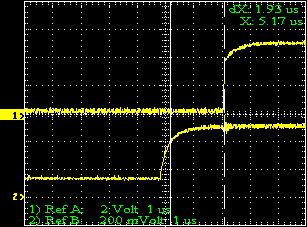
Performance
Minimum delay between rising edge pf PPS (marking second boundary) and Synchronization signal transition was 2µs. Maximum delay was 5µs. This was measured on a Pentium xx MHz desktop PC. The GPS was connected directly to the PC by 8m cable; an ordinary multiconductor was used - no coax for the PPS signal. Due to distibuted cable capacitance, the PPS signal suffers slower risetime as cable length increases. The effect is clearly visible in fig. 2. Routing the PPS in a coax will probably improve matters, ref. fig 1. In the junction box close to the PC some kind of waveshape regeneration would also be needed, combined with a cable terminating resistor. |
| Download This is a raw alpha version program. Bug reports or improvements can be emailed to olem@ifjf.uib.no.
|
| What next .... This system was developed (in a hurry!) as a replacement for a Syncronization unit that was left behind on the University research vessel. By divine intervention one of the ship's cranes suffered a breakdown, and the ship had to enter a norwegian port. The unit could then be recovered, putting further development of the replacement system on hold. Anyhow, the program source code may be utilized in later projects. |
Last update Aug. 24, 2000 by OM