IntroductionThese two systems works together during seismic data acqusition:
Geometry setting on seismic field data is called "an often unpleasant task" in this Seismic Unix manual. There is some truth to this, unfortunately ... What complicates matters are these possible error conditions:
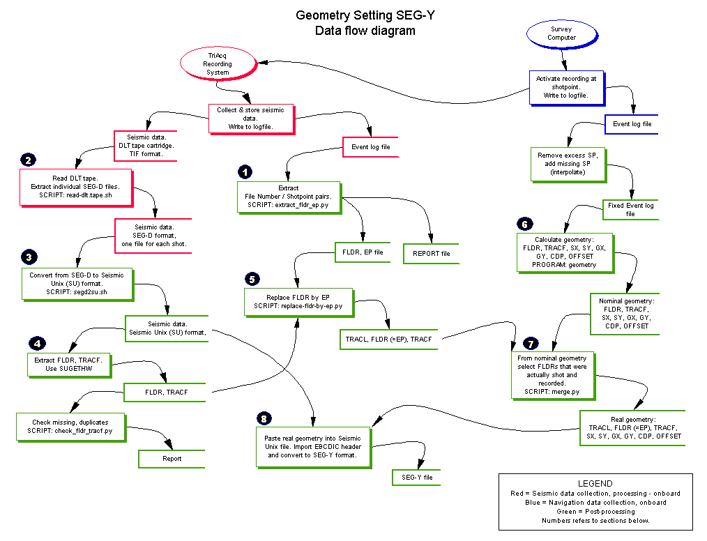
The data- and processing flow is shown below.
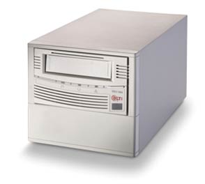
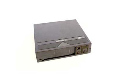
1. Establish link between seismic recording number and shotpoint numberPrior to the survey, a shotpoint geometry is set when line start- and endpoints, and shot interval, is specified. When actually shooting the line, the survey computer will continuously read ship's position from GPS, and compare it to pre-determined shotpoint positions. When certain criteria are met, the survey computer issues a shot command that activates seismic source and recording system.The ship is steered manually. Thus the position of actual shotpoints will deviate from those set by pre-determined geometry. It's the real shotpoint positions that will be used in subsequent geometry setting procedure. A map showing real shotpoint positions can look like this.  Fig. 1. Map of real shotpoint locations (click to enlarge). One piece of information is crucial. The relation between seismic dataset and shotpoint number must be established - otherwise the locations of the seismic traces are unknown. The problem is that shotpoint number is not recorded in the seismic datafiles. This information is only available in logfile that the TriAcq recording system generates. The seismic datasets contains a file counter that increments for each recording. A missing shotpoint goes unnoticed, as fas as the seismic recording is concerned. The TriAcq log file that ties file counter and shotpoint number can lok like this (link to file): 03:12:13 WN EVGEN Norstar drifting 0.401977 03:12:32 IN RCCONTR Stream 1: Shot 113, File 113 recorded on /dev/rmt/1n 03:12:54 IN RCCONTR Stream 1: Shot 114, File 114 recorded on /dev/rmt/1n 03:12:57 WS EVGEN Wrong checksum, discarded norstar block 03:13:08 IN STRIN No event to shot at seisbase time 1104200694 03:13:19 WN EVGEN Norstar drifting 0.489014 03:13:19 IV EVGEN Missed some shotnumber(s) between 114 and 116 03:13:30 WS STRCONTR Shot# 116: 1 Status Word parity errors 03:13:38 IN RCCONTR Stream 1: Shot 116, File 115 recorded on /dev/rmt/1n 03:13:40 WN EVGEN Norstar drifting -0.754992 03:13:52 WS STRCONTR Shot# 117: 1 Status Word parity errors 03:14:00 IN RCCONTR Stream 1: Shot 117, File 116 recorded on /dev/rmt/1n 03:14:21 IN RCCONTR Stream 1: Shot 118, File 117 recorded on /dev/rmt/1nThe important sections in yellow. Notice that shotpoint 115 is missing. We extract shot/file pairs using the script extract_fldr_ep.py. The script is invoked by typing e.g. ./extract_fldr_ep.py Line25-0_27aug2005_0249where Line25-0_27aug2005_0249 is the name of the TriAcq logfile. Two files will now be generated by adding extensions to the input file: The first contains a list of file/shotpoint pairs. E.g., from the listing above, these pairs are extracted: 113 113 114 114 115 116 116 117 117 118 118 119The file is given extension .fldr_ep. 'fldr' and 'ep' refers to SEG-Y trace headers. 'fldr' (field record number) here means file number, and 'ep' (energy point) means shotpoint number. The second file reports all errors: # Extracting File No (assigned by Triack recording) and Shotpoint No (assigned by Survey Computer), from: Line25-0_27aug2005_0249 # Checking for duplicate and missing shots and files FN=53: First FileNo (Assigned by TriAcq when writing SEG-D data to tape) SP=53: First shotpoint (from Survey Computer) SP=116: Missing shot SP=342: Missing shot SP=441: Missing shot SP=484: Missing shot SP=518: Missing shot SP=638: Missing shot SP=727: Last shotpoint (from Survey Computer) FN=721: Last FileNumber (Assigned by TriAcq when writing SEG-D data to tape)The report will specify the SP where faults were detected. So, at SP=116, it was found that we had a missing shotpoint (115). This is the most common error. The following procedures will take care of this error. Let's move on to the next stage. 2. Extract SEG-D shot files from tapeSeismic data are stored on DLT-IV tapes while shooting.
Extract all shots on tape to SEG-D files (one file for each shot) using the script read-DLT-tape.sh. Most likely this has already be done during the survey. First make directory where SEG-D files will be placed. Copy script to this directory. Invoke it by typing: ./read_DLT-tape.sh 53 721The parameters are first and last file numbers, respectively. We refer to example in section 1 above. Check that you've got a long list of files. 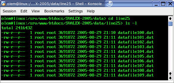 Fig. 2. Extracting SEG-D files from DLT-tape; one file for each shot. Using mc (Midnight Commander) , it's easy to veryfy that datafile53.dat is the first file, and that datafile721.dat is the last one: 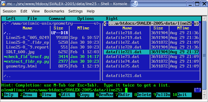 Fig. 3. Verifying that datafile721 was the last file extracted. In addition to missing shotpoints we can also encounter (much more rarely) a situation with missing files. In that case files with highest number(s) will have zero size. (This will be treated in a leter version of this document). 3. Convert SEG-D files to SU (Seismic Unix) fileNext stage is to assemble all individual SEG-D shot files into one Seismic Unix file. The Seismic Unix file format is derived from SEG-Y - the difference is explained here.First examine Line25/SVALEX-2005 log sheet to determine the exact beginning/end shotpoints. Click to enlarge: 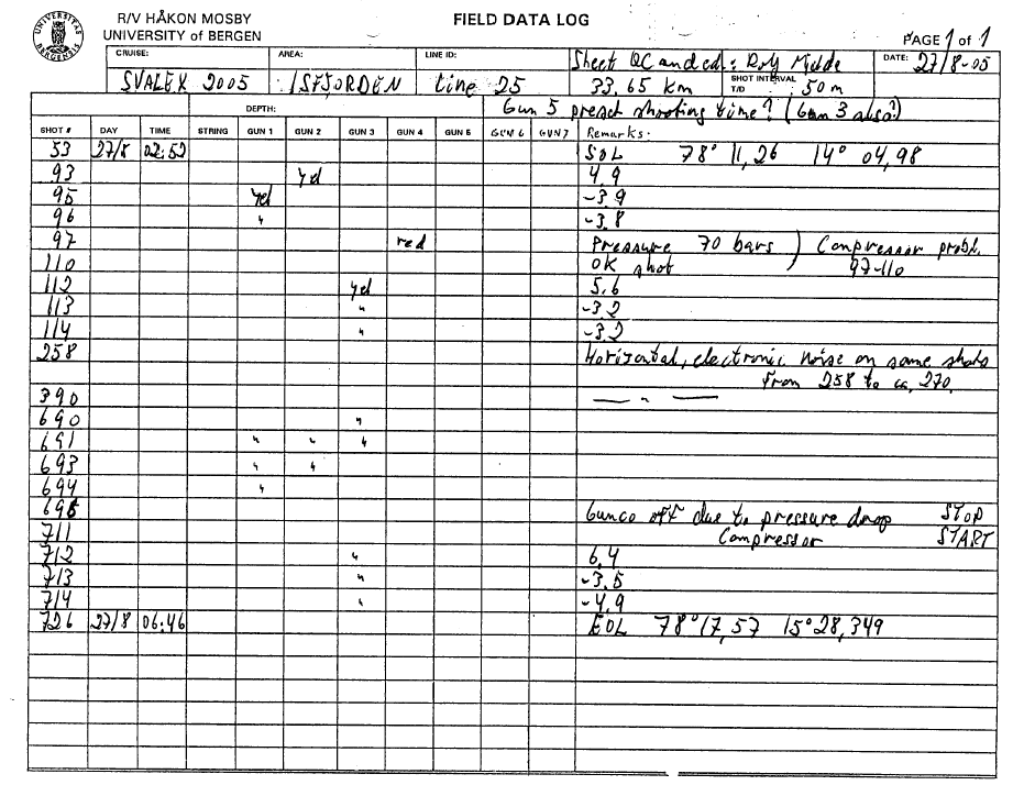 Fig. 4. Examine logsheet to determine first/last shotpoint number (click to enlarge). We see that SP=53 is SOL (Start of Line), and SP=726 is EOL (End of Line). In section one, however, we found that last SP was 727. This means that one excess shot was recorded. And here's what important: SP=726, the EOL shotpoint, corresponds to File or recording number 720. This is the effect of missing shotpoints. Convert SEG-D files to SU file using the script segd2su.sh. First create a directory that will hold the Seismic Unix file. It's a good idea to first ensure that you have enough space on the disk; type df -h in terminal window. The Line-25 SU file will consume about 3.8 GByte. Copy script to this directory. Open script in editor and change relevant parameters: path=/srv/www/htdocs/SVALEX-2005/data/ line=line25 # set directory where data files are stored first=53 # set first file number last=720 # set last file number tape=./svalex-2005-$line-$first-$last.su ns=6144 # set number of samples per trace dt=2000 # set sample inverval (microseconds) ntrpr=240 # set number of traces per recordInvoke the script by typing ./segd2suFor Line25/SVALEX-2005 tt will take about 5 minutes to complete the script on a 2.8 MHz P4 (type cat /proc/cpuinfo to see MIPS rating of your machine). The last lines will tell the total number of traces and shots converted: segdread: 160320 traces from tape segdread: 668 shots (160320 traces) from tape segdread: tape closed successfully Done! olem@linux:/DATA/SVALEX-2005/Line25>We now have a large Seismic Unix File: olem@linux:/DATA/SVALEX-2005/Line25> ls -l svalex-2005-line25-53-720.su -rw-r--r-- 1 olem users 3978501120 2006-02-01 14:01 svalex-2005-line25-53-720.suThe Seismic Unix SURANGE command will show which traceheaders are in use, and their min/max range. olem@linux:/DATA/SVALEX-2005/Line25> surange < svalex-2005-line25-53-720.su 160320 traces: fldr=(53,720) tracf=(1,240) trid=1 ns=6144 dt=2000 year=2005 day=239 hour=(2,6) minute=(0,59) sec=(0,59)This is what we expect. 'fldr' from 53 to 720, 'tracf' from 1 to 240. 4. Extract trace header parameters from SU (Seismic Unix) fileWe now need to extract 'fldr' and 'tracf' traceheaders from the SU file. This information, together with the file/shotpoint pairs we extracted from the TriAcq log file in section 1, will later be used to select proper lines in the geometry file.Extract 'fldr' and 'tracf' and store in file line25-fldr-tracf.dat by typing: sugethw < svalex-2005-line25-53-720.su key=fldr,tracf output=geom > line25-fldr-tracf.datThe output file will hold two columns of values, like this, showing the seven first lines: 53 1 53 2 53 3 53 4 53 5 53 6 53 7Next, look for:
olem@linux:/DATA/SVALEX-2005/Line25> ./check_fldr_tracf.py line25-fldr-tracf.dat
****************************************************************************************************
Checking fldr and tracf extracted from SU file trace headers.
Looking for duplicate and missing fldr and tracf.
Program will halt if errors are detected. You must sort out problems before you continue.
****************************************************************************************************
fldr=53: First fldr found
fldr=720: Last fldr found
No of traces: 160320
Everything OK so far! 5. Replace 'fldr' by 'ep'Next stage is to replace 'fldr' we got in section 4, by 'ep' - or shotpoint - we found in section 1. The goal is to tie each shot to a specific shotpoint. Use the script replace-fldr-by-ep.py:./replace-fldr-by-ep.py Line25-0_27aug2005_0249.fldr_ep line25-fldr-tracf.dat > line25-tracl-fldr-tracf.dat In more detail, the two input files are like this:
For each fldr in the file to the left, collect all tracf in file to the right, where the two fldr are identical. Replace fldr by ep. Finally, add tracl (counting traces) and write to file. The output file will be:
The lower part of the output file listing shows how missing SP=115 makes itself felt. In the next stage we make a geometry file based on all real shotpoints - independent of any missing recordings. In the final stage we modify this geometry file to take missing shotpoints into account. 6. Nominal geometryThis section is based on work by Dr. Bent Ole Ruud. Make nominal geometry based on shotpoint file. First remove any excess shotpoints in the start and end of line (ref. section 1). Then extract shot point data (sp, sx, sy) from navigation data, assuming positions are in UTM format (the search pattern /^0/ will select lines that start with zero - here is a description of awk seach pattern): awk '/^0/ {print $1, $4, $5}' line25-navdata-fixed.dat > line25-spsxsy.dat
Make a new file containing nominal geometry, with these parameters: olem@linux:/DATA/SVALEX-2005/Line25> ./geometry Name of file with UTM coordinates of shot points: line25-spsxsy.dat First shot is 53 Last shot is 726 Distance between antenna and source (m): 70 Distance between source and first hydrophone group (m): 125 Distance between hydrophone groups (m): 12.5 Number of hydrophone groups: 240 Distance between CMPs (m): (Typically half the distance between hydrophone groups) 6.25 CMP number below first shot point: 1000 Name of output file: line25-nominal-geometry.dat Output file will look like this: 53 1 478987 8679463 478870 8679421 979 125 53 2 478987 8679463 478858 8679417 978 137 53 3 478987 8679463 478846 8679412 977 150 53 4 478987 8679463 478834 8679408 976 162 .. 114 238 481852 8680511 478953 8679450 1230 3087 114 239 481852 8680511 478941 8679446 1229 3100 114 240 481852 8680511 478929 8679442 1228 3112 115 1 481900 8680525 481781 8680487 1475 125 115 2 481900 8680525 481769 8680483 1474 137 115 3 481900 8680525 481757 8680478 1473 150 .. 115 238 481900 8680525 479000 8679467 1238 3087 115 239 481900 8680525 478988 8679463 1237 3099 115 240 481900 8680525 478976 8679459 1236 3112 116 1 481947 8680540 481828 8680503 1483 125 116 2 481947 8680540 481816 8680499 1482 137 116 3 481947 8680540 481804 8680495 1481 150 7. Real geometryNominal geometry file will have entries for all possible shotpoints. We have to remove entries that are associated with missing shotpoints. The script merge.py will accomplish this task. Invoke the script by typing: ./merge.py line25-tracl-fldr-tracf.dat line25-nominal-geometry.dat > line25-real-geometry.dat Output (still line 25) looks like this - TRACL, FLDR (=EP), SX, SY, GX, GY, CDP, OFFSET: 1 53 1 478987 8679463 478870 8679421 979 125 2 53 2 478987 8679463 478858 8679417 978 137 3 53 3 478987 8679463 478846 8679412 977 150 4 53 4 478987 8679463 478834 8679408 976 162 .. 14878 114 238 481852 8680511 478953 8679450 1230 3087 14879 114 239 481852 8680511 478941 8679446 1229 3100 14880 114 240 481852 8680511 478929 8679442 1228 3112 14881 116 1 481947 8680540 481828 8680503 1483 125 14882 116 2 481947 8680540 481816 8680499 1482 137 14883 116 3 481947 8680540 481804 8680495 1481 150 Notice how missing SP=115 manifests itself. 8. Convert to SEG-YFirst convert real geometry to binary format: a2b n1=9 < line25-real-geometry.dat > line25-real-geometry.bin Now paste real geometry into Seismic Unix file: sushw key=tracl,fldr,tracf,sx,sy,gx,gy,cdp,offset infile=line25-real-geometry.bin < svalex-2005-line25-53-720.su > tmp.su Now prepare the EBCDIC header file - here is the version we will use for line 25. The parameters that varies are in yellow. C 1 CLIENT SVALEX-2005 LEG1 COMPANY IFG/UIB CREW NO C 2 LINE 25 AREA ISFJORDEN MAP ID C 3 REEL NO DAY-START OF REEL YEAR 2005 OBSERVER C 4 INSTRUMENT: MFG GECO MODEL TRIACQ SERIAL NO C 5 DATA TRACES/RECORD 240 AUXILIARY TRACES/RECORD CDP FOLD C 6 SAMPLE INTERNAL 2 MS SAMPLES/TRACE 6144 BITS/IN BYTES/SAMPLE 2.5 C 7 RECORDING FORMAT SEGD-2 FORMAT THIS REEL SEG-Y MEASUREMENT SYSTEM C 8 SAMPLE CODE: FLOATING PT FIXED PT FIXED PT-GAIN CORRELATED C 9 GAIN TYPE: FIXED BINARY FLOATING POINT OTHER C10 FILTERS: ALIAS HZ NOTCH HZ BAND - HZ SLOPE - DB/OCT C11 SOURCE: TYPE NUMBER/POINT POINT INTERVAL C12 PATTERN: LENGTH WIDTH C13 SWEEP: START HZ END HZ LENGTH MS CHANNEL NO TYPE C14 TAPER: START LENGTH MS END LENGTH MS TYPE C15 SPREAD: OFFSET MAX DISTANCE GROUP INTERVAL C16 GEOPHONES: PER GROUP SPACING FREQUENCY MFG MODEL C17 PATTERN: LENGTH WIDTH C18 TRACES SORTED BY: RECORD CDP OTHER C19 AMPLITUDE RECOVEY: NONE SPHERICAL DIV AGC OTHER C20 MAP PROJECTION: UTM (WGS84) ZONE ID 33X COORDINATE UNITS M C21 PROCESSING: C22 PROCESSING: C23 C24 C25 C26 C27 C28 C29 C30 C31 C32 C33 C34 C35 C36 C37 C38 C39 C40 END EBCDIC Export to SEG-Y by typing: segyhdrs ns=6144 dt=2000 ntrpr=240 bfile=binary hfile=/dev/null /bin/cp ascii.header header segywrite tape=SVALEX-2005-line25.segy verbose=1 vblock=240 endian=0 conv=1 < tmp.su Before copying this SEG-Y file to DVD or other media, it's useful to generate MD5 checksum so that receiver can veryfy that file integrity is intact. Use this command: md5sum SVALEX-2005-line25.segy > SVALEX-2005-line25.segy.md5 To verify, write: md5sum -c SVALEX-2005-line25.segy.md5 NOTE:
|
||||||||||||||||||