Gravity meter S-99
Power Supply & Platform Control
Unit test points
Click here to get a PDF version
version of this document.
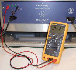
You need at least a multimeter to perform these tests;
an oscilloscope is, however, best.
1. Power supply test
The power supply has three testpoints, phase
A, B and C. These are the gyro spin motor
excitation voltages. The motor is 3-phase AC,
driven by 200 Hz sinusoids, 120º phase shifted.
The phase voltages can be measured in two
ways, a) Neutral (0V) to Line, or b) Line to
Line.
1.1 Phase voltage
|
 1.1.1 Using multimeter. 1.1.1 Using multimeter.
Meter setup: AC. Measure between 0V and each phase, and
between phases. Also measure frequency, if the multimeter
has this capability.
TBD = To be determined.
|
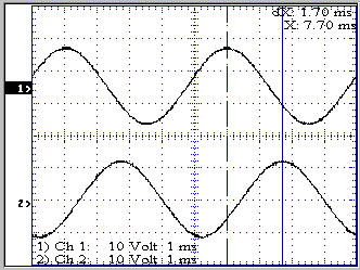
1.1.2 Using oscilloscope.
Measure between 0V and each phase.
Note: Do not measure between phases by
attaching the probe's ground clip to one of the
phases - you risk making a short circuit if the
scope's ground is tied to power supply 0 V.
Instead make a differential measurement using two
probes, ground clips to 0V, and then subtract
ch.2 from ch.1.
The figure on the right shows phase A and B.
Peak-to-peak value is approx 24 V. The phase
difference can be measured to (1.7ms/5ms)*360º =
122º; the cursor readout is however not very
accurate, so this just indicates the 120º phase
shift.
|
 |
| |
|
 The signals are not "pure"
200 Hz sinusoids. If a spectral decomposition
(FFT) is performed the harmonic distortion can be
measured. The amplitude of the 3rd harmonic (600
Hz) should be less then 1% of the fundamental
(200 Hz). It was measured to 1.2% (refer to
figure on the right). The signals are not "pure"
200 Hz sinusoids. If a spectral decomposition
(FFT) is performed the harmonic distortion can be
measured. The amplitude of the 3rd harmonic (600
Hz) should be less then 1% of the fundamental
(200 Hz). It was measured to 1.2% (refer to
figure on the right).
Data from Tektronic oscilloscope TDS210.
Calculated by Tektronix's WaveStar software.
|
| |
|
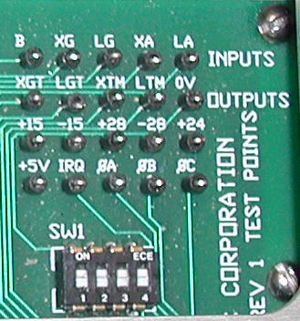
2. Platform control unit tests
The testpoints are located on a small printed
circuit board inside the Platform Control Unit,
below the metal lid - see the figure to the
right.. Learn the "nomenclature" - it
makes testing easier:
X = Cross
L = Long
G = Gyro
A = Accelerometer
T = Torque
M = Motor
Note that "torque" applies to two
components: a) The motors that keep the platform
level, and b) the gyros, where the torque input
signal is used to compensate for long-term
horizontal reference changes (e.g. earth
rotation). If you're not aware of this it can be
a bit confusing.
Program switches SPRING TENSION and ALARM set
to OFF.
|
 |
| |
|
| No. |
Test-
points |
Ref. |
Scope
image |
Description |
| 1 |
B |
0V |
|
CPI sensor output, identical to front
panel meter. Slew the beam to end
positions.
Range: -9.8 Vdc .. 9.9 Vdc. |
| 2 |
XG |
0V |
Yes |
Cross Axis Gyro output signal
By turning off the Cross Torque Motor
switch you can see a 200Hz, 1V
peak-to-peak sine wave on an
oscilloscope, when the platform is
rotated in the cross axis direction.
Chooce IRQ as trigger for the
oscilloscope.
Multimeter (select AC measurements): 0.4
Vrms max. output. |
| 3 |
LG |
0V |
|
Long Axis Gyro output signal, similar
to XG. |
| 4 |
XA |
0V |
|
Cross Axis Accelerometer output.
By turning off the Cross Torque Motor
switch you can see a DC-voltage on an
oscilloscope or a voltmeter, when the
platform is rotated in the cross
direction.
Signal range: -12.6Vdc .. 11.9Vdc. |
| 5 |
LA |
0V |
|
Long Axis Accelerometer output,
similar to XA.
Signal range: -12.6Vdc .. 12.0Vdc. |
| 6 |
XGT |
0V |
Yes |
Cross Axis Gyro Torque - input signal
to gyro. Due to time integral this signal
build slowly to saturation.
Cross Torque Motor switch = OFF.
Signal range: -6.5 Vdc .. 8.7 Vdc |
| 7 |
LGT |
0V |
|
Long Axis Gyro Torque, similar to
XGT.
Signal range: -6.0 Vdc .. 8.2 Vdc |
| 8 |
XTM |
0V |
Yes |
Cross Axis Torque Motor. Signal to
motor that keeps platform level in cross
axis.
Cross Torque Motor switch = OFF.
Signal range: -1.6 Vdc .. 1.5 Vdc |
| 9 |
LTM |
0V |
|
Long Axis Torque Motor, similar to
XTM.
Signal range: -1.9 Vdc .. 1.6 Vdc |
| 10 |
IRQ |
0V |
Yes |
Interrupt Request. This is a digital
clock signal.
Only measure with oscilloscope!
Square wave, approx. 50% duty cycle, 200
Hz, 0-4V peak-to-peak. |
| 11 |
 |
0V |
|
Gyro spin motor excitation voltage.
200 Hz, 24V peak-to-peak, 8.1V +/- 0.3V
rms.
> 40dB attenuation of 3rd harmonic
600Hz (means that 3rd harmonic's
amplitude should be less then 1% of 1st
harmonic's amplitude).
Note: Identical to
the Power Supply Unit testpoints! |
| 12 |
 |
0V |
|
As Phase A, with 120º phase shift. |
| 13 |
 |
0V |
|
As Phase B, with 120º phase shift. |
|
DC voltages ±28V, ±15, +24V, +5V can also be checked
via UltraSys program.
University
of Bergen
Institute of Solid
Earth Physics
Allé gt. 41, N-5007 Bergen, NORWAY
Tel: (+47) 5558 3420 / 21
Fax: (+47) 5558 9669
Email: elab@ifjf.uib.no
April 6, 2001 (OM)
|
