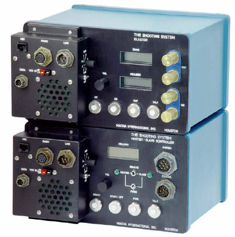
BLASTER SYSTEM
We will use Macha's "Shooting System".
 Macha Shooting System
⚠ (:toc:)
<:vspace>
!Testing
----
Attach:blaster-confirmation-timebreak.png"Blaster test"<br />''Blaster test''
<:vspace>
* Upper yellow trace is Calculated Timebreak, output from Master (unit on recording site).
* Blue trace is Confirmation Timebreak (also output from Master).
* Lower trace is secondary side of cap transformer - will indicate onset of cap current.
* Time resolution: 1 ms/div.
<:vspace>
The oscilloscope is set in "Persist = Infinite" mode, which means that each recording will just be added to the display. If we trigger on Confirmation Timebreak middle trace) any jitter between the trigger signal, and the Cap Current trace (lower), will be visible. We have made approx 5 recordings. The offset between Confirmation Timebreak and Cap Current signal is about 1.8 ms and fairly constant. So the blaster seems to be working fine. A constant offset with small jitter < 200 us is acceptable.
<:vspace>
<:vspace>
!Detecting Cap current
----
<:vspace>
We follow a tip on page 21, section 5.3.R of the "I/O Technical Manual, Series 200, Seismic Source Synchronizer System, Installation and Maintenance":
<:vspace>
-> <pre class='escaped'>... A more convernient way, especially when the use of explosives is to be avoided, is to use an
isolation transformer by winding ten feet of two-wire cap lead on a pencil. (The wiring length is not
critical - build up layers about two inches long). One of the cap wires forms the transformer primary,
the other wire forms the secondary. Connect the ends of one of the cap leads (same wire) to the
DECODER cap terminals. Connect the ends of the other wire pair to a galvo. When the DECODER "FIRES",
current will be induced in the galvo winding of the transformer thus causing a galvo deflection
at "FIRE" time.</pre>
<:vspace>
<:vspace>
<:vspace>
Attach:trafo-no-diode.png"Isolation transformer to measure cap current"<br />''Isolation transformer to measure cap current.''
<:vspace>
In the figure above, cap current runs in red and black leads in bottom right part of the picture. The isolation transformer, top, uses blue wires for the primary side, and yellow for the secondary side. The coax cable, lower left, is routed to the oscilloscope.
<:vspace>
In the following tests the cap wire is short-circuited; only the transformer is used.
<:vspace>
The cap current starts abruptly and then decreases gradually. The induced seconday voltage will reflect the rate of change in the current, so it will be large at the onset of the current.
<:vspace>
<:vspace>
<:vspace>
<:vspace>
<:vspace>

