|
Surveys and data Instruments
Support to other department sections Support Dr. Scient. thesis Contribution to "Scientific infrastructure"
Obsolete, kept for reference
Last update: April 30, 2025, at 08:49 AM |
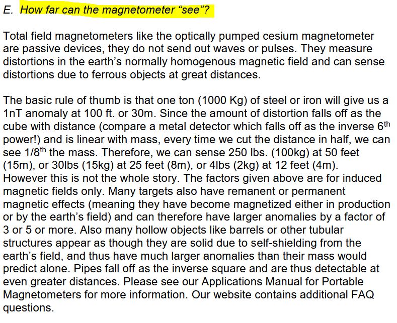
MAGNETOMETERCESIUM MAGNETOMETER GEOMETRICS G-882Specifications, link to manual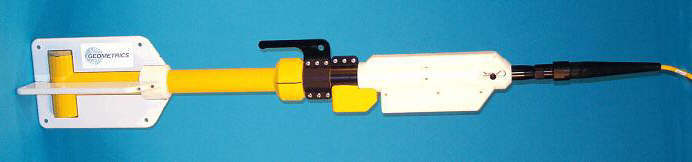 Geometrics G-882 Marine Magnetometer
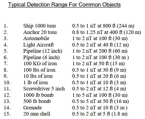
Specifications, excerpt from page 5 of the G-882 manual rev. H. (local copy - check for latest version). Maximum cable length for telemetry"Geometrics marine magnetometers are powered by low-voltage (24v) sources and are equipped for two-way communication using an RS-232 serial data format. This power/communication method employs a 5 conductor tow cable and is limited by power and signal loss to cable lengths of 1000 ft (305m) or less. The low voltage/serial data scheme has several advantages but will not support operation on longer cables. To permit operation on cables longer that 1000 ft. Geometrics provides the telemetry system described in this manual." Detection ranges
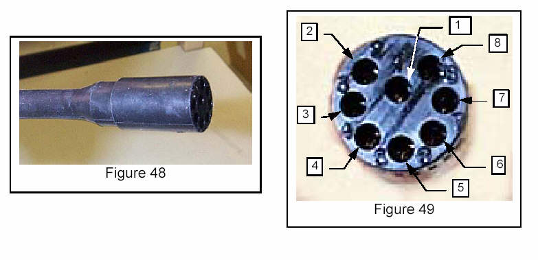
G-882 sensor orientationRef. G-882 User Manual, p. 31, section 4.3.1 "Sensor Positioning in Relation to the Dip Angle of the Survey Area". Geometrics recommend that the sensor be oriented such that Earth’s magnetic field lines (H field) are centered in its active zone. Quoting from p. 29 of the manual: The sensor head should be oriented so that the earth's field vector arrives at an angle of from 15° to 75° to the optical axis of the sensor. The earth’s field vector is vertical at the poles, between 50º and 60º in the mid latitudes and horizontal at the magnetic equator. (See CSAZ program on Magnetometer CD). Adjusting the sensor for the polar and mid-latitude regions is simple, by orienting the sensor either at 45º (rotating the main tube 1/8th turn for polar regions) or 0º (no rotation required at mid-latitudes) respectively. Picture below shows sensor orientation suitable for operation in the 22.5° - 67.5° region. Maps on p. 34 in the manual shows magnetic field inclination and intensity for the survey area. 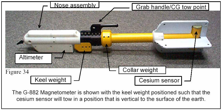 G-882 wiring diagramThis information is provided in case the mag fish tow cable should be used for other purposes. The tow cable wiring diagram is given on p. 107 of the G-882 User Manual: 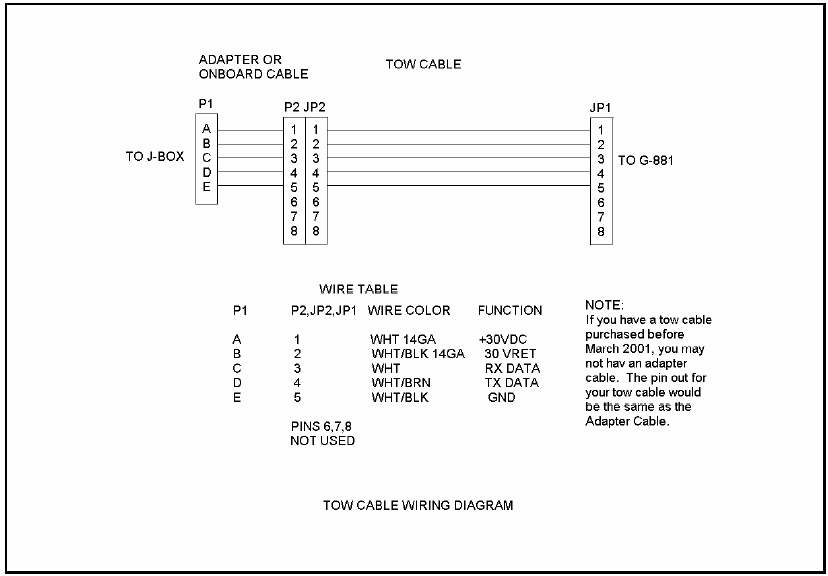 G-882 Tow cable wiring diagram
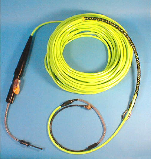
G-882 tow cableThe wet side of the cable consist of a cable clevis assembly attached to towing point on mag fish, and a connector. Details about clevis assembly and connector will be provided later. Tow cable specifications:
Geometrics recommends a winch if the length of the tow cable exceeds 120 m (400 ft). Use "Kellems grip" (aka "Chinese fingers") to attach the tow cable a winch. DC / DATA Junction Box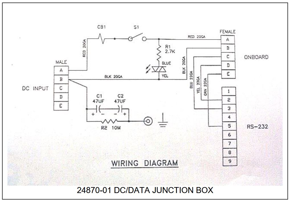 From page 112 of manual VER H. G-882 spare partsStock as of 18 Sept 2008:
-------------------------------------------------------------------------------------
MFR P/N     QTY  UNIT   DESCRIPTION
-------------------------------------------------------------------------------------
24780-01     1   ea     Power/data junction box (JB) for G-882
24810-02     2   ea     AC/DC Power Unit, 95 - 230 Vac, 50/60 Hz for 24780-01 G-882 JB
                        30V 1.9A output
21-201-019   2   ea     SP06A-14-5P (SR)
                        Connector that mates "Onboard cable" JB input connector
21-201-020   2   set    SP06A-14-5S (SR)
                        Connector that mates "Power" JB input connector
21-236-410   2   ea     MCIL8F 8 PIN FEM PIGTAIL SUBC.
                        Connector that mates connector on ship's side of tow cable
28-602-002  10   ea     Cotter pin, 1/16 x 3/4" 316 98355A020
                        Small, for top cover linch pins
28-602-001  10   ea     Cotter pin, 1/8 x 1 3/4" 316 SS
                        Large, for nose tow pin
21-236-420   5   ea     Locking sleeve MCDLSF, for connector on ship's side of tow cable
21-236-421   5   ea     Locking sleeve MCDLSM, for connector on ship's side of tow cable
21-236-412   5   ea     Dummy conn 8 pin female
21-236-413   5   ea     Dummy conn 8 pin male

Shipping crate:
25969-01                G-882 SHPNG CRT W/CRDL PNTD WHITE

Kits:
24825-04                G-882 SHIP KIT

Deck cable:
60-453-101              CABLE, FM071003-2CP 6-WIRE GREEN
G-882 S/N: 882150 repair logRepairs can either be done at Geometrics, or their U.K. representative Geomatrix. Here is a (Word format) Packing/Proforma Invoice template that could be useful.
RV "H. MOSBY": DISTANCE FROM SENSOR TO NAV. REFERENCE POINT
On RV "Håkon Mosby", the distance from magnetometer towfisk to navigation system reference point is thus (195m + 24m) = 219 meter.  RV "Håkon Mosby": Gravitymeter - which is the navigation system reference point - is placed at frame 40. Frame distance is 60cm.
MAGNETOMETER WINCH Magnetometer winch onboard RV "G.O. SARS" (click to enlarge). Magnetometer winch specificationsWe have two identical magnetometer winches. The oldest was delivered in 1996, and the newest in 2009. Each winch is furnished with slip-ring box and hydraulic motor. Specifications, 2009 mag winch:
Winch foundation, measured on RV "G.O. SARS"Click to open drawing (PDF format) made of "as-built" magwinch foundation on RV "G.O. SARS":  Magwinch foundation, as measured on RV "G.O. SARS". Click to open PDF document. Mag winch foundation on RV "G.O. SARS", facing aft - click to enlarge: Winch foundation, manufacturer's drawing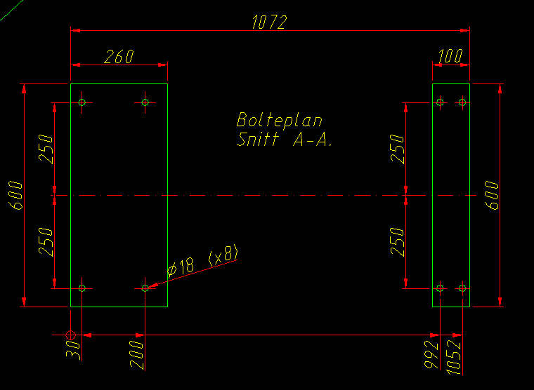 Detail from Karmøy Winch drawing no.: M361804.DWG Winch pictures, 22 March 2010Click to see large images.     Mag winch slipring boxThe Geometrics G-882 has a 5-conductor tow cable with layout as shown below (excerpt from page 108 of G-882 Manual). Power lines have max 32 Vdc, 0.75 Amp at start-up and 0.5 Amp thereafter. RX/TX are low voltage/current signal lines.
Click images to see larger versions     GEOMETRICS G-801 (phased out)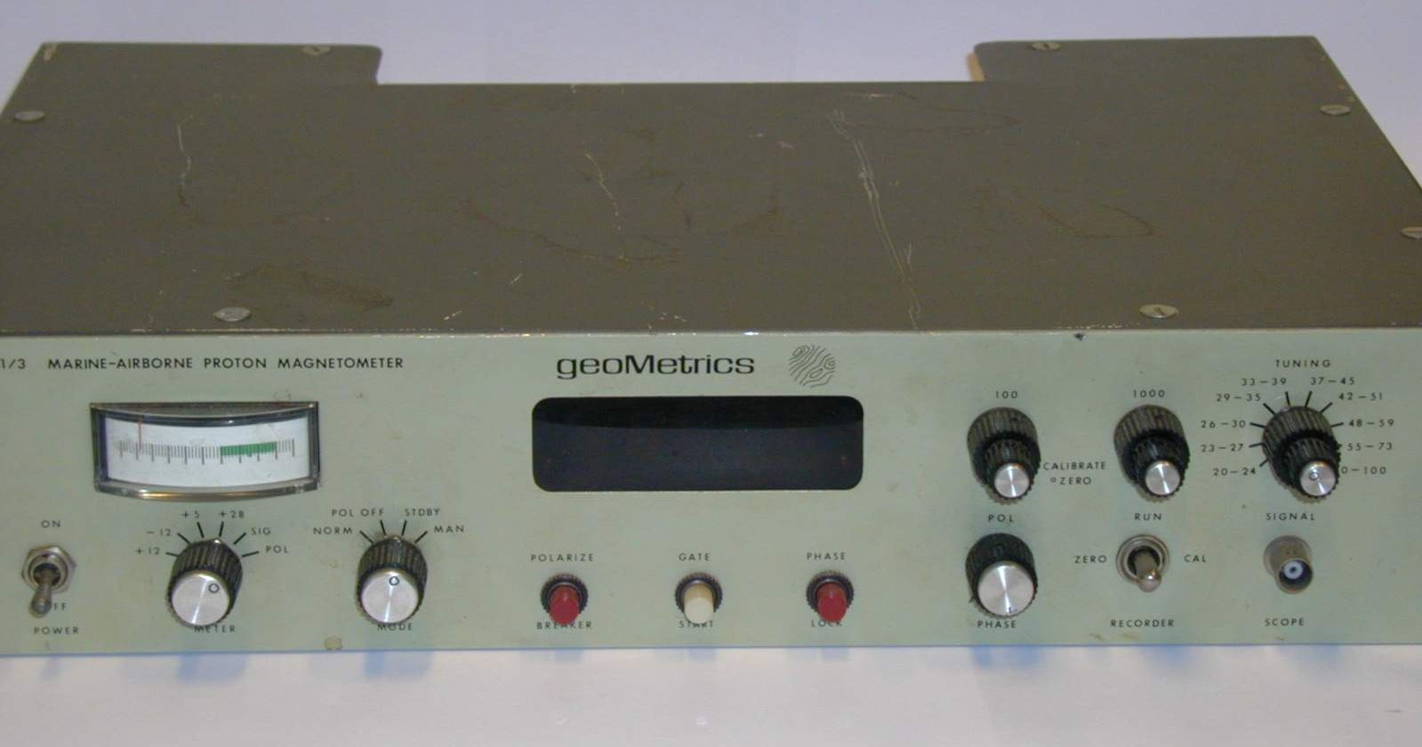 Click to see larger image
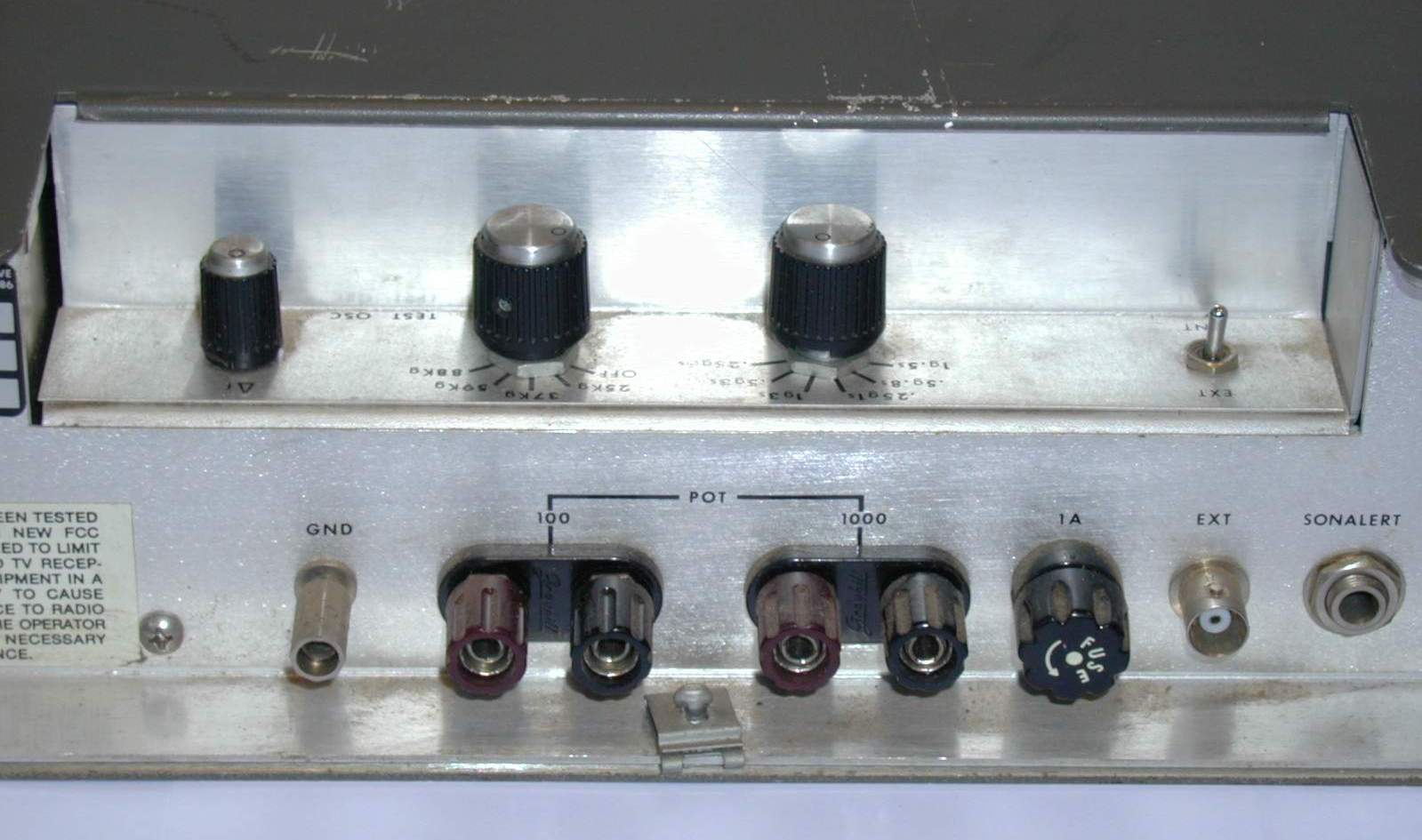 Rear view 1 (click to enlage) 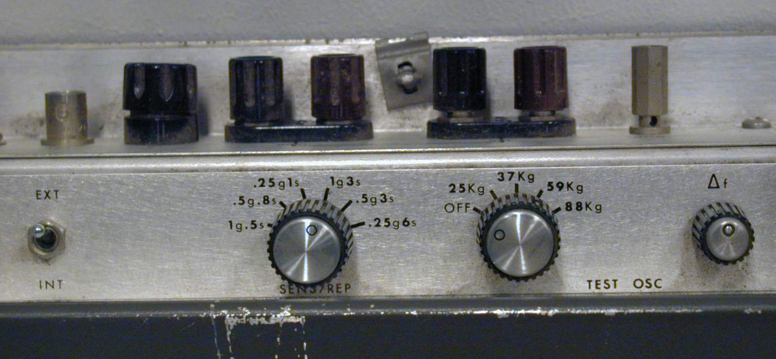 \\ \\ Rear view 2 (click to enlage) MISC.RS-232 to RS-422 converter: MOXA TCC-80/80I media converter
Links
Contact information
|
 .
.