|
Surveys and data Instruments
Support to other department sections Support Dr. Scient. thesis Contribution to "Scientific infrastructure"
Obsolete, kept for reference
Last update: April 30, 2025, at 08:49 AM |
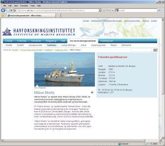
Open photo album to see similar instrument layout on OBS-2014 survey.  OBS-2014 photo album. Click to open. RV "HÅKON MOSBY" - CONTACT INFORMATION
RECORDING LOG SHEET
TIME STAMPING OF SHOT EVENTSThe Ocean Bottom Seismographs that are deployed on the sea floor, or recorders on land, keep time using very accurate internal clocks, or GPS. It is necessary to obtain time stamp of every shot event in order to process data later on. The time stamping is done by routing the "SCOPE TIME BREAK" from GUNCO signal to a GPS based event recorder. The "SCOPE TIME BREAK" signal is emitted on "Zero time" - the nominal firing moment of all guns, according to the timing method that has been selected from GUNCO menus. It is emitted in sequence after two GUNCO input control signals have been asserted correctly - the CLOSURE and FIRE signal. The relationship between these three signals is shown below. 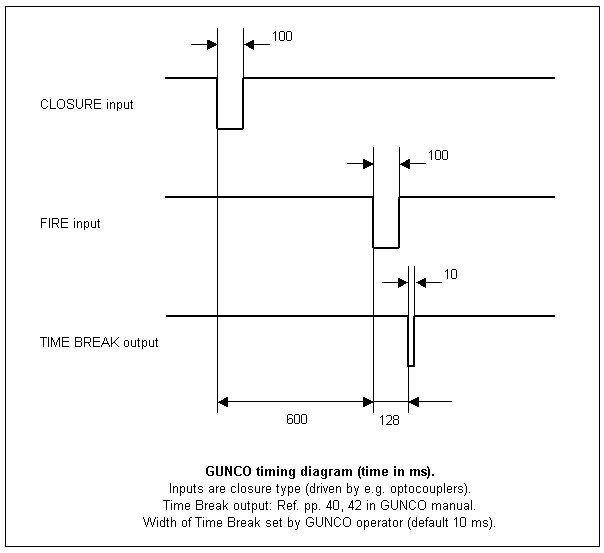 Gun Controller timing diagram. So the falling edge of the SCOPE TIME BREAK signal is used as input for the time stamping unit.  Click to open documentation of primary time stamping equipment Ashtech ProFlex Lite DG14.
GRAVITY METER Air/Marine Gravitymeter LaCoste & Romberg, S-99 Synchronizing SPRING TENSION valuesRemember to synchronize SPRING TENSION value in software with the actual spring tension as shown on the counter on the left side of the sensor platform. Daily logLog sheets can be downloaded from this page: http://www.geo.uib.no/eworkshop/gravitymeter/index.php?n=Main.LogSheets Sensor installed in vessel
Beam Zero and Gain adjustment (L&R Sensor)Refer to gravity meter manual. K-checkRefer to gravity meter manual. Base readings; land gravity meter
GUN CONTROLLER "GUNCO"GUNCO connector wiringThe key to understand the GUNCO connector system is to see how the front slot positions of the MSIBG cards corresponds to the connectors on the rear side - see figure below. We normally only use one MSIBG card located in slot #5. This card will thus have sensors connected on SI3 (labelled "STBD1,2"), and solenoids on SO5 (labelled "STBD 1").  GUNCO connector principle.
GUNCO rack wiring (rear view)Current systemClick to open PDF document: 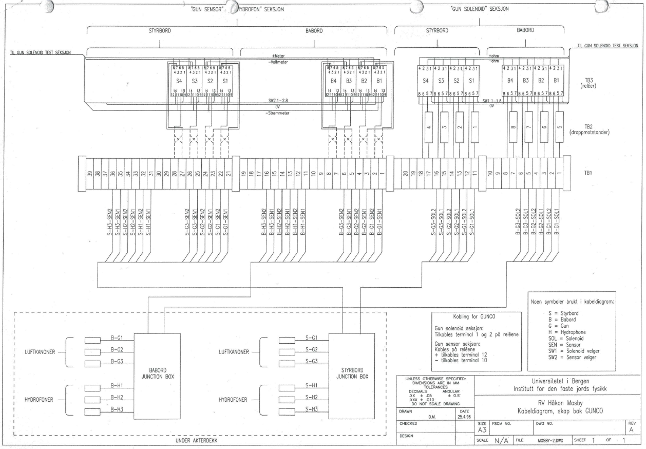 GUNCO Rack cabling. Click to open PDF version. Old systemThe difference is that relays have been added for the airgun solenoid test unit, which allows the operator to monitor sensor voltage and current, and measure resistance to solenoid. 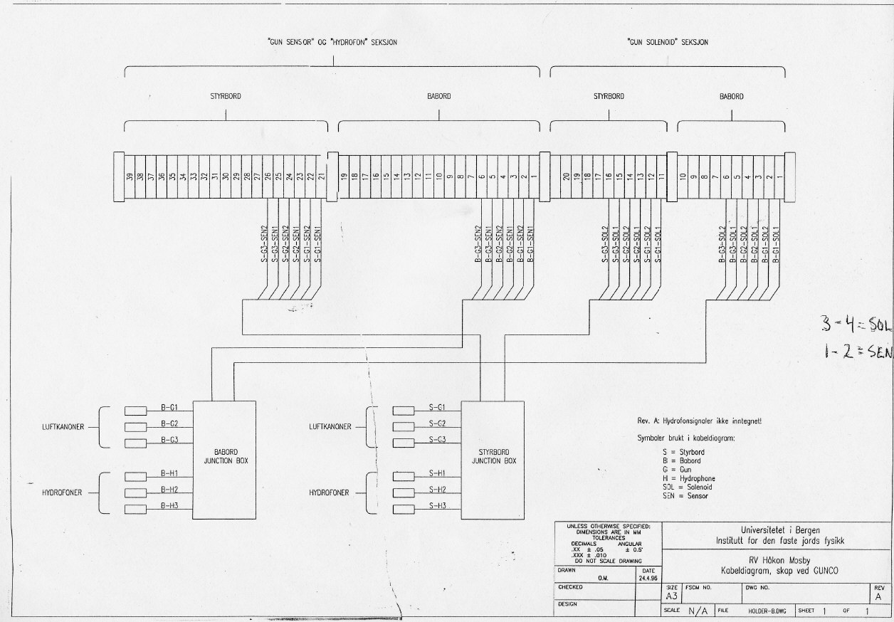
GUNCO Sensor DisplayThis is what a GUNCO sensor display could look like. Click to see larger version. NOTE: Airgun no. 1,2 and 6 is OK. No. 5 has crossfeed from the solenoid pulse; the "crosfree blanking" feature of the GUNCO is activated (red area), causing any signal that appears within the read zones to be ignored.  GUNCO sensor display. Click to enlarge.
MINI-STREAMER RECORDING SYSTEMWe will use a two-channel mini-streamer, and record data on a Geometrics GEODE, which is controlled from a PC laptop running Windows. 
SYNC UNITThe Sync Unit is placed between the EIVA Survey computer and GUNCO. It receives a trigger command from the survey computer in the form of an ASCII "A" sent over RS232 serial line. The Sync Unit was designed in 1998 and at that time also interfaced two other systems, a magnetometer and a recording system (DFS V) that have both been phased out long time ago. The LCD menu hasn't been updated and thus still provides options that reflects those now unused systems (so don't get confused). At that time the Survey Computer by mistake sometimes issued double shot event triggers a couple of seconds after the proper trigger. This caused the GUNCO to fire when it wasn't supposed to. To prevent this situation the Sync Unit was furnished with a software timer that defined a period in which new triggers were ignored after the first one. The green LED on the front panel is lit during this "trigger ignored" interval. This survey requires 12.5 meter shot point distance, which means the "trigger ignored" setting must be reduced from it's current value of approx 8 seconds, down to 1 second. This is explained in section below.
Routing of CLOSURE and FIRE signal to GUNCOThe GUNCO is now controlled by the "Triacq" recording system of the 3km streamer. Two BNC cables must be relocated so it will become slave to the Sync Unit instead:
Schematics
CPU card inside: "Flashlite-V25"The CPU card is "Flashlite-V25" made by JK Micro. This product has long since been replaced by other versions. The documentation cannot be located (here's a report from someone using it in 2000). But it's quite similar to its replacement, Flashlite 186: How to alter the "trigger ignored" time parameterThe Flashlite 186 CPU card is in reality a tiny MSDOS computer. In initial mode we get contact with the card via serial RS232 cable. A terminal program will then get access to the normal DOS prompt. A user program is automatically started by following instructions found on page 2 of the Flashlite 186 manual: When power is applied to the Flashlite or when it is reset, the board goes through its initialization procedure and then starts DOS. A simple (read-only) AUTOEXEC.BAT file is executed and then the board is ready to use. The batch file performs several functions before the user is given control. The DOS search path is set, the DOS prompt is set, the CTRL-C flag (discussed later in this manual) is checked and finally, an attempt is made to execute a file named STARTUP on the B: drive. This provides a convenient way for custom applications to execute immediately after initialization of the Flashlite. If you wish to have your application start automatically, create a batch file named STARTUP.BAT that invokes the program. Here is the crucial point. The program accepts command line parameters. The first parameter instructs the card to operate in either "OBS" mode (that we use now) or "DFS" mode (which is deprecated). And the second parameter sets the "trigger ignored" duration, in seconds. So in the STARTUP.BAT file the last line will be the program name followed by two parameters, "OBS" and "8" (or close to that figure). The last parameter must be set to "1" instead. If it's omitted the program uses a default value of 15 seconds instead. How can the STARTUP.BAT file be edited? First the program that is running on the CPU card must be terminated or prevented from starting. That can be done in two ways:
The edit process itself is described on page 15 of the Flashlite 186 manual: EDIT.COM EXAMPLE: B:\>edit test.bat FlashLite Line Editor v1.0 Enter h for help New File: test.bat >> i 0: @echo Batch file being processed... 1: mytsr 2: myapp 3: ^Z >> l 0: @echo Batch file being processed... 1: mytsr -> 2: myapp >> q Save before exit (Y,n): y File Saved B:\> Here is a description of the vintage MSDOS EDLIN command line editor.
|
||||||||||||||