
|
Surveys and data Instruments
Support to other department sections Support Dr. Scient. thesis Contribution to "Scientific infrastructure"
Obsolete, kept for reference
Last update: April 30, 2025, at 08:49 AM |
Click to open photo album from OBS-2016 Marine Seismic Survey. SURVEY, VESSEL
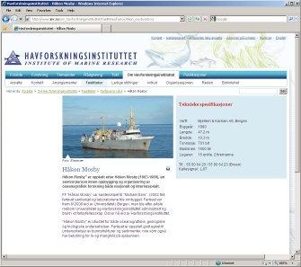
RV "HÅKON MOSBY" - CONTACT INFORMATION
UiB-GEO SCOPE OF SUPPLY, INSTRUMENTATION
AIRGUN SOURCE / MINI-STREAMER GEOMETRYOverview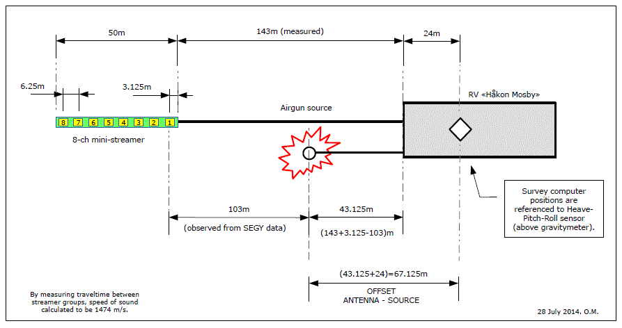 OBS-2014 acquisition geometry; layout of 2016 geometry expected to be identical. Download PDF version. Airgun source
UTM Zone, reference point on vesselAll UTM data are relative to UTM Zone 32W. All coordinates are also relative to the position of the gravity meter on board the ship.  Gravitymeter is placed at frame 40. Frame distance is 0.6 m. Thus, gravity meter is 40 x 0.6 m = 24.0 m from the stern. Airguns offset distanceAirguns are positioned 43 meters behind the stern. We have to add offset between gravity meter and stern, to obtain the total offset between source and positions given in navdata files. Thus, total offset between source and positions given in nav data files is: 43 m + 24.0 m = 67 m. MINI-STREAMER & SEISMIC RECORDING SYSTEMMini-streamer 8 channels Click to enlarge. Ref streamer description. Recording systemMini-streamer data is recorded on Geometrics GEODE, which is controlled from a PC laptop running Windows.  Click to see Geode product description.
Primary recording system:
Backup recording system:
Time stamp recording system:
TIME STAMPING OF SHOT EVENTS - OVERVIEWThe Ocean Bottom Seismographs that are deployed on the sea floor, or recorders on land, keep time using very accurate internal clocks, or GPS. It is necessary to obtain time stamp of every shot event in order to process data later on. The time stamping is done by routing the "SCOPE TIME BREAK" from GUNCO signal to a GPS based event recorder. The "SCOPE TIME BREAK" signal is emitted on "Zero time" - the nominal firing moment of all guns, according to the timing method that has been selected from GUNCO menus. It is emitted in sequence after two GUNCO input control signals have been asserted correctly - the CLOSURE and FIRE signal. The relationship between these three signals is shown below. 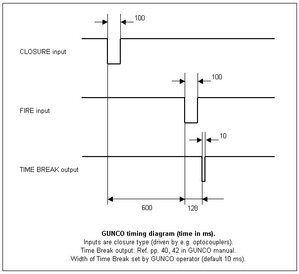 Gun Controller timing diagram. So the falling edge of the SCOPE TIME BREAK signal is used as input for the time stamping unit. Diagram of time stamping system - hardware and software UiB OBS-2014 survey: Overview of time stamping hardware and software. The Survey Computer is the master of the system. All parameters for the seismic line - start and end positions, interval between shot points are entered by the operator. When the line is activated, the survey computer takes care of the rest by issuing the necessary triggering signals to other units in the system, and generating proper log files. Processed nav data is delivered in modified UKOOOA P1/90 format. Download the P1/90 specifications from here. In the P1/90 file, the parameters associated with a shot point is put in a single line of text, however the formatting is very compact making the identification of the individual parameters a bit difficult. GEOMAR has established an unofficial extension of the standard to accommodate the time stamp information that OBS surveys require. These time stamps are put in record positions that are normally assigned for other purposes, but can be "sacrificed" if need be. See more detailed explanation below. Ashtech time stamp unit "ProFlex Lite DG14" Click to open documentation of primary time stamping equipment Ashtech ProFlex Lite DG14.
COM port pin out Ashtech DG14 COM port pin out, from page 13 in manual. Unit configurationCheck options installed by issuing the $PASHQ,RIO command, ref.page 15 in the manual. Here is the response: $PASHR,RIO,DG16,DD04,,TOPUB_LE_C__YXDR___I,71168612DG6201222026*17 Old Ashtech GG24 config; Setup for Ashtech GG24 : =========================== ; ; Reset with default settings $PASHS,RST ; ; Set receiver in mixed GPS/GLONASS mode $PASHS,SYS,MIX ; ; Set elevation mask to 10 degrees $PASHS,PEM,10 ; ; Send NMEA message GGA on port C $PASHS,NME,GGA,C,ON ; ; Send NMEA message SAT on port C $PASHS,NME,SAT,C.ON ; ; Send NMEA message ZDA on port C $PASHS,NME,ZDA,C,ON ; ; Set NMEA "send message interval" to 1 Hz $PASHS,NME,PER,1.0 ; ; Set event marker signal to falling edge $PASHS,PHE,F ; ; Set 1PPS trigger edge to falling edge $PASHS,PPS,01.00,+000.0000,F ; ; Output Event marker message on port C $PASHS,NME,TTT,C,ON ; ; Output Signal-to-Noise-Ratio (SNR) in dB*Hz $PASHS,SNR,DBH ; ; Output Event marker time in GPS-system-time $PASHS,TSC,GPS ; ; Save settings in battery backed-up memory $PASHS,SAV,Y Configuration 8 July 2016$PASHQ,RIO $PASHR,RIO,DG16,DD04,,TOPUB_LE_C__YXDR___I,71168612DG6201222026*17 $PASHS,SYS,MIX $PASHR,NAK*30 $PASHS,RST $PASHR,ACK*3D $PASHS,SYS,MIX $PASHR,NAK*30 $PASHS,PEM,10 $PASHR,ACK*3D $PASHS,PHE,F $PASHR,ACK*3D $PASHS,PPS,01.00,+000.0000,F $PASHR,ACK*3D $PASHS,NME,TTT,C,ON $PASHR,ACK*3D Secondary time stamping systemAIRGUN CONTROLLER - "GUNCO"GUNCO connector wiringThe key to understand the GUNCO connector system is to see how the front slot positions of the MSIBG cards corresponds to the connectors on the rear side - see figure below. We normally only use one MSIBG card located in slot #5. This card will thus have sensors connected on SI3 (labelled "STBD1,2"), and solenoids on SO5 (labelled "STBD 1").  GUNCO connector principle. GUNCO rack wiring (rear view)Current systemClick to open PDF document: 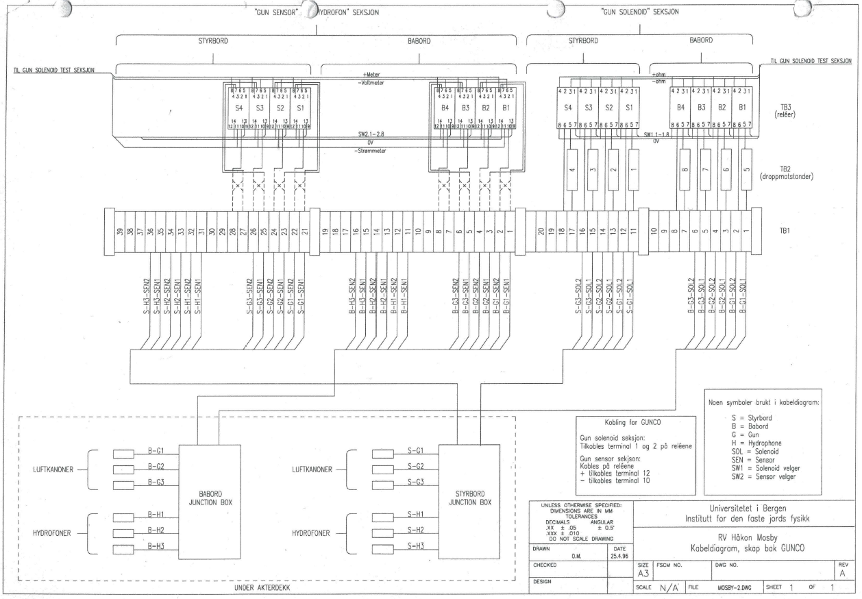 GUNCO Rack cabling. Click to open PDF version. Old systemThe difference is that relays have been added for the airgun solenoid test unit, which allows the operator to monitor sensor voltage and current, and measure resistance to solenoid. 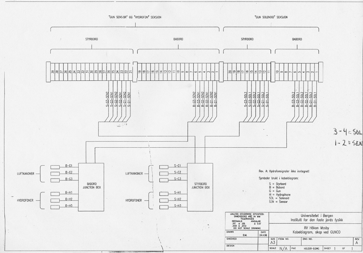 GUNCO Sensor DisplayThis is what a GUNCO sensor display could look like. Click to see larger version. NOTE: Airgun no. 1,2 and 6 is OK. No. 5 has crossfeed from the solenoid pulse; the "crosfree blanking" feature of the GUNCO is activated (red area), causing any signal that appears within the read zones to be ignored.  GUNCO sensor display. Click to enlarge. SYNC UNITThe Sync Unit is placed between the EIVA Survey computer and GUNCO. It receives a trigger command from the survey computer in the form of an ASCII "A" sent over RS232 serial line. The Sync Unit was designed in 1998 and at that time also interfaced two other systems, a magnetometer and a recording system (DFS V) that have both been phased out long time ago. The LCD menu hasn't been updated and thus still provides options that reflects those now unused systems (so don't get confused). At that time the Survey Computer by mistake sometimes issued double shot event triggers a couple of seconds after the proper trigger. This caused the GUNCO to fire when it wasn't supposed to. To prevent this situation the Sync Unit was furnished with a software timer that defined a period in which new triggers were ignored after the first one. The green LED on the front panel is lit during this "trigger ignored" interval. This survey requires 12.5 meter shot point distance, which means the "trigger ignored" setting must be reduced from it's current value of approx 8 seconds, down to 1 second. This is explained in section below.
Routing of CLOSURE and FIRE signal to GUNCOThe GUNCO is now controlled by the "Triacq" recording system of the 3km streamer. Two BNC cables must be relocated so it will become slave to the Sync Unit instead:
Schematics
CPU card inside: "Flashlite-V25"The CPU card is "Flashlite-V25" made by JK Micro. This product has long since been replaced by other versions. The documentation cannot be located (here's a report from someone using it in 2000). But it's quite similar to its replacement, Flashlite 186: How to alter the "trigger ignored" time parameterThe Flashlite 186 CPU card is in reality a tiny MSDOS computer. In initial mode we get contact with the card via serial RS232 cable. A terminal program will then get access to the normal DOS prompt. A user program is automatically started by following instructions found on page 2 of the Flashlite 186 manual: When power is applied to the Flashlite or when it is reset, the board goes through its initialization procedure and then starts DOS. A simple (read-only) AUTOEXEC.BAT file is executed and then the board is ready to use. The batch file performs several functions before the user is given control. The DOS search path is set, the DOS prompt is set, the CTRL-C flag (discussed later in this manual) is checked and finally, an attempt is made to execute a file named STARTUP on the B: drive. This provides a convenient way for custom applications to execute immediately after initialization of the Flashlite. If you wish to have your application start automatically, create a batch file named STARTUP.BAT that invokes the program. Here is the crucial point. The program accepts command line parameters. The first parameter instructs the card to operate in either "OBS" mode (that we use now) or "DFS" mode (which is deprecated). And the second parameter sets the "trigger ignored" duration, in seconds. So in the STARTUP.BAT file the last line will be the program name followed by two parameters, "OBS" and "8" (or close to that figure). The last parameter must be set to "1" instead. If it's omitted the program uses a default value of 15 seconds instead. How can the STARTUP.BAT file be edited? First the program that is running on the CPU card must be terminated or prevented from starting. That can be done in two ways:
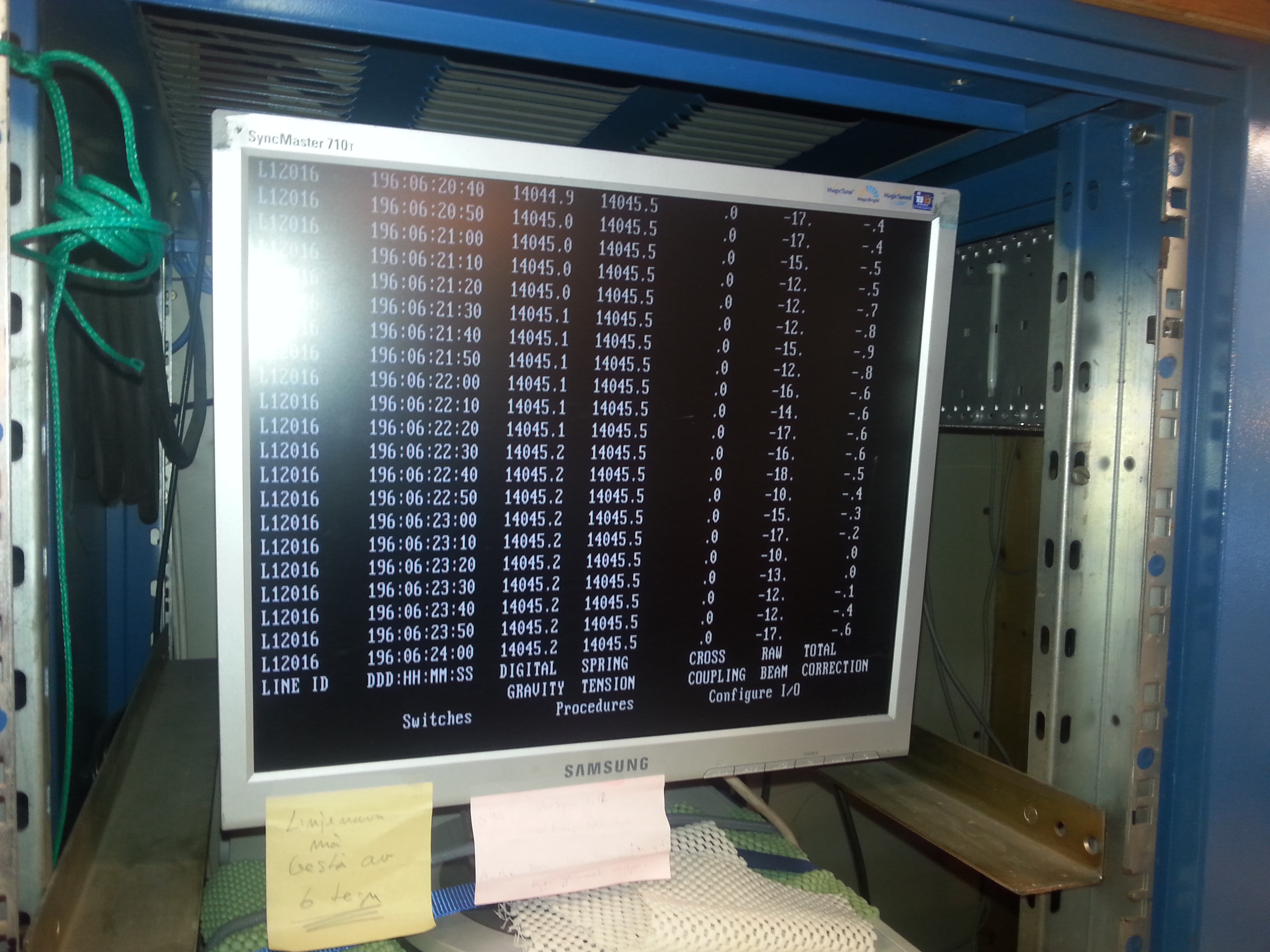
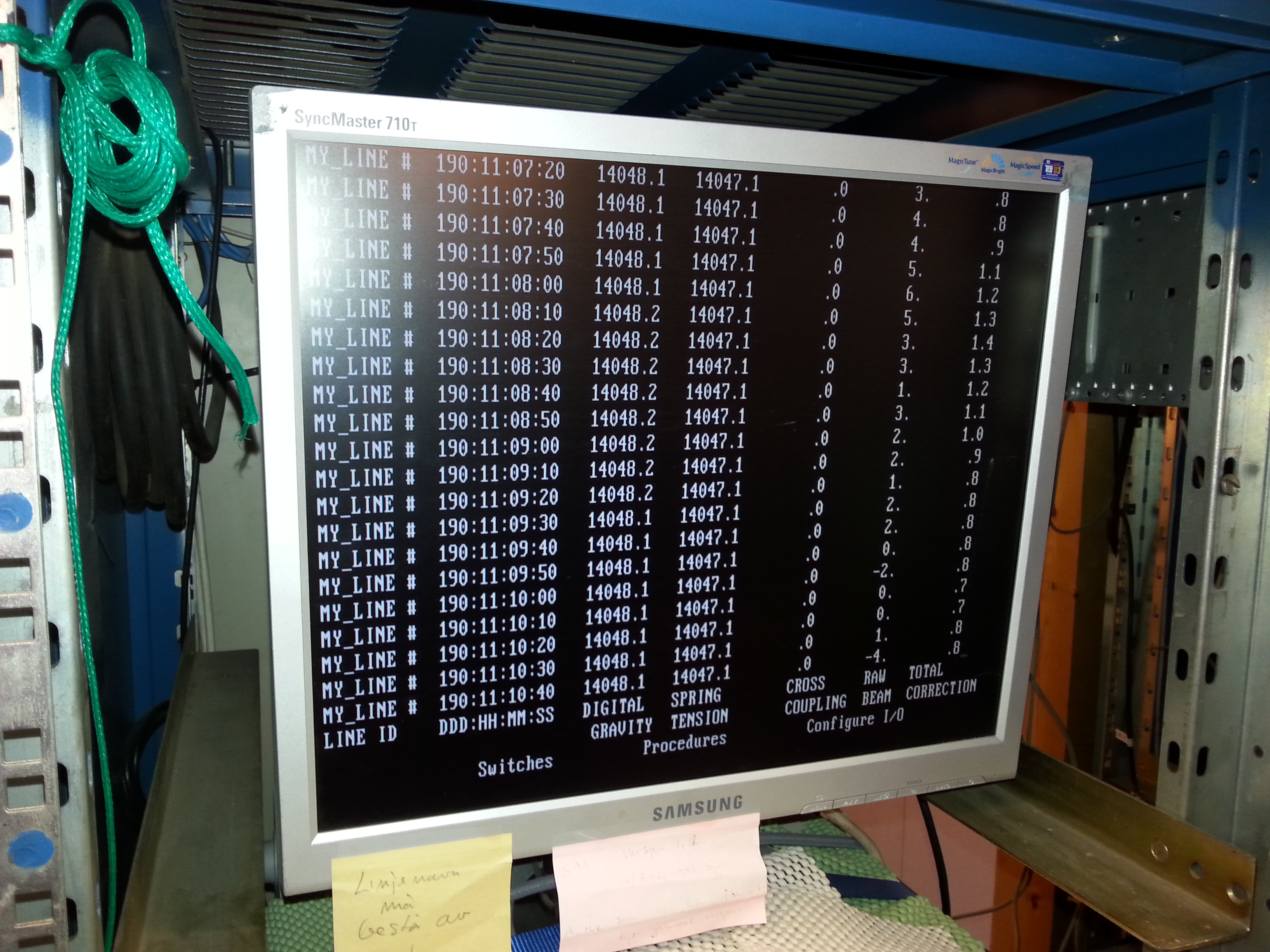
The edit process itself is described on page 15 of the Flashlite 186 manual: EDIT.COM EXAMPLE: B:\>edit test.bat FlashLite Line Editor v1.0 Enter h for help New File: test.bat >> i 0: @echo Batch file being processed... 1: mytsr 2: myapp 3: ^Z >> l 0: @echo Batch file being processed... 1: mytsr -> 2: myapp >> q Save before exit (Y,n): y File Saved B:\> Here is a description of the vintage MSDOS EDLIN command line editor. GRAVITY METER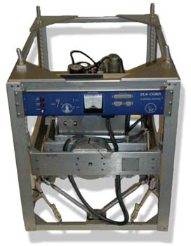 Air/Marine Gravitymeter LaCoste & Romberg, S-99 Synchronizing SPRING TENSION valuesRemember to synchronize SPRING TENSION value in software with the actual spring tension as shown on the counter on the left side of the sensor platform. Daily logLog sheets can be downloaded from this page: http://www.geo.uib.no/eworkshop/gravitymeter/index.php?n=Main.LogSheets Sensor installed in vessel
Beam Zero and Gain adjustment (L&R Sensor)Refer to gravity meter manual. K-checkRefer to gravity meter manual. Base readings; land gravity meter
Land gravimeter calibration table Calibration table land gravimeter L&R S/N: G-936. Click to enlarge. Converting the counter reading to milliGalsExcerpt from p.1-9 of G-936 Instruction Manual:
  If the counter reading is 2654.32, look at the calibration table for your meter. Remember that each meter has its own unique table.

                          Portion of calibration table
     _____________________________________________________________________________
    /                                                                             \
   /    Counter reading           Interval factor           Cumulative value       \

            2500   ..............     1.00794    .............   2519.42
    +---->  2600   ..............     1.00799    .............   2620.21  <---+
    |       2700   ..............     1.00805    .............   2721.01      |
    |       2800   ..............     1.00811    .............   2821.82      |
    |                                                                         |
    |    Divide the reading into two parts:                                   |
    |                                                                         |
    +---->  2600.00                               2620.21  <------------------+
            + 54.32                                +54.75  <----+
            -------                               -------       |
            2654.32                               2674.96       |
                                                                |
         Interval factor x reading within interval              |
                                                                |
                               1.00799 x 54.32 = 54.75  <-------+
Bodø Gravity Reference Stations Click to follow Bodø map link, with three Gravity Stations marked. "BODØ P" is obsolete.
There is also reference to "BODØ P" in the list of Norwegian Gravity Stations, with coordinates:
This Gravity Station is obsolete as that position is on the apron of Bodø Airport. Gravity meter base readings Bodø
Daily logOBS-2016-gravitymeter-daily-check-log.pdf 
PRODUCTION OF UKOOA P1/90 NAV DATA FILEUKOOA P1/90 navdata formatOutput from nav data processing should be in UKOOA P1/90 format, slightly modified to accommodate three decimals in time value. The UKOOA P1/90 format specification can be downloaded from SEG. It's a fixed-position format without any <SPACE> or <TAB> delimiters between fields, so it can be hard to read. However, by inserting appropriate comment field in the header, it can be made much more legible, as this example shows. The first part is the header; the individual shot points are at the end (six lines) : H0100 SURVEY AREA ISFJORDEN, SVALBARD H0101 SURVEY DETAILS SVALEX-2005 H0102 VESSEL DETAILS R.V. HAAKON MOSBY H0104 STREAMER DETAILS 240 CH GECO NESSIE-3 H0200 SURVEY DATE AUGUST - SEPTEMBER 2005 H0201 FILE CREATED 16-Jan-2006 H0202 FILE VERSION UKOOA P1/1990 H0300 CLIENT SVALEX-2005 H0400 GEOPHYSICAL CONTRACTOR UNIVERSITY OF BERGEN, NORWAY H0500 POSITIONING CONTRACTOR N/A H0600 POSITIONING PROCESSING O.M. UNIVERSITY OF BERGEN, DEPT OF EARTH SCIENCE H0700 POSITIONING SYSTEM H0700 SURVEY COMPUTER SOFTWARE NAVIPAC, EIVA, DENMARK H0700 H0800 SHOTPOINT POSITION CENTRE OF SOURCE H1000 CLOCK TIME UTC H0900 OFFSET SHIP SYSTEM TO SP 70.0 M BEHIND H1200 SPHEROID AS SURVEYED A,1/F WGS-84 Spheroid 6378137.000 298.2572236 H1300 SPHEROID AS PLOTTED A,1/F WGS-84 Spheroid 6378137.000 298.2572236 H1400 GEODETIC DATUM AS SURVEYED WGS-84 H1500 GEODETIC DATUM AS PLOTTED WGS-84 H1700 VERTICAL DATUM SL : ECHO SOUNDER H1800 PROJECTION 001 UTM NORTHERN HEMISPHERE H1900 ZONE 33X NORTHERN HEMISPHERE H2000 GRID UNIT 1 METRE H2001 HEIGHT UNIT 1 METRE H2002 ANGULAR UNITS 1 DEGREES H2200 CENTRAL MERIDIAN 15 DEG E H2600 H2600 00011111111112222222222333333333344444444445555555555666666666677777777778 H2600 78901234567890123456789012345678901234567890123456789012345678901234567890 H2600 -NAME-><->---<-SP-><---LAT--><--LONG---><--EAST-><-NORTH-><-DEP><D><TIME>- SLine34-05 18781022.23N 141348.31E 482384.58677774.7 215.8242180734 SLine34-05 19781023.47N 141353.32E 482416.98677812.8 214.7242180755 SLine34-05 20781024.73N 141358.24E 482448.78677851.4 212.3242180816 SLine34-05 21781026.00N 1414 3.08E 482480.08677890.4 209.6242180837 SLine34-05 22781027.28N 1414 7.88E 482510.98677929.7 207.6242180858 SLine34-05 23781028.53N 141412.83E 482543.08677968.1 206.2242180919 UKOOA P1-90 navdata format structure. The shot point (SP) parameter, for instance, is located from column 20 to 25, as shown below. The two column numbering lines, together with the parameter name line, is an aid in determining the column position of the different parameters. These three "legend" lines are not common - they are only inserted by the software we use to generate UKOOA P1/90 files. +--------> Column 20 | | +---> Colomn 25 | | 222222 012345 <-SP-> 18 19 20 21 22 23 Updated standard: P1/11The P1/90 standard was updated some years ago:
We have not evaluated the new standard yet. "OBS" modification of UKOOA P1/90 navdata formatOBS refraction surveys means that source (airguns on ship) and receivers (OBS placed on the bottom, or on land, as an extension of the profile) must maintain a common, accurate - to the nearest millisecond - time base. This is accomplished by special oven-controlled oscillators in the OBS instruments, and GPS locked clocks in land based instruments. On board the ship, the exact time of the shot point is recorded by two time-tagging systems operating in parallel (details provided in table of geophysical equipment above). The time field in the UKOOA P1/90 format only accommodates seconds without decimals. The format has been modified to permit storage of shot times with six decimal places, of which only the three most significant decimals are used. An example of modified file: H2600 FILE FORMAT MODIFIED TO INCLUDE SHOTPOINT TIME IN COLUMNS [7..19] H2600 H2600 00011111111112222222222333333333344444444445555555555666666666677777777778 H2600 78901234567890123456789012345678901234567890123456789012345678901234567890 H2600 <--SP TIME--><-SP-><---LAT--><--LONG---><--EAST-><-NORTH-><-DEP><D><TIME>- SSM-1 101921.956000 99632728.92N 74033.97E 732982.37045135.6 171.3297101921 SSM-1 102109.690000 100632728.28N 74019.50E 732783.87045101.1 172.4297102109 SSM-1 102251.455000 101632728.66N 740 5.07E 732583.57045098.3 176.4297102251 "EIVA" Survey Computer shot event log filesThe format of these shot point log files is as follows: Event Date Time Easting Northing St.d. Gyro Dal Dol Kp Object Data ----------------------------------------------------------------------------------------------------------- 000774 2016.07.10 14:54:03.200 0648120.91 07516414.04 00.90 337.2 23356.01 -51.16 076.050 "Filtered " 0086.72 14241.33 "" 01 000775 2016.07.10 14:55:29.762 0648016.56 07516531.21 00.90 308.5 23506.46 -06.63 076.200 "Filtered " 0087.11 14241.93 "" 01 000776 2016.07.10 14:56:47.782 0647878.86 07516593.77 00.80 308.3 00104.40 -26.24 076.350 "Filtered " 0088.52 14243.41 "" 01 000777 2016.07.10 14:58:07.241 0647753.91 07516676.84 00.90 318.0 00254.38 -21.76 076.500 "Filtered " 0090.26 14246.09 "" 01 Parameters are given in first line. Most are self-explanatory, except these:
The last item in each line ("" 01) can be ignored. Shot time stamp filesThe airgun controller (GUNCO) provides a signal that indicates when the shot was fired. Technically, it's a TTL-level signal, normally in a HIGH state (approx 5 Volt); a short pulse of approx 100ms duration will be emitted at every shot, with the falling edge indicating the nominal shot point. Yes, individual air guns may fire a certain amount of time before or after this nominal shot point, but if this deviation is too large - in our case +/- 2 ms off target - the GUNCO will provide av audio and visible warning that the shot should be discarded. The signal is routed to a special GPS receiver (Ashtech model ProFlex Lite DG14) furnished with a trigger input line. The trigger can be specified at falling or trailing edge of a pulse. When a trigger occurs the units transmits a record of the time stamps on one of its serial ports. Time stamp values are NOT provided in UTC format, but in the format that is used internally by the GPS system - so called "GPS time". The difference is that "leap seconds" are inserted at irregular intervals into the UTC timing in order to keep UTC in sync with Earth's rotation (which is gradually slowing down, but not in a linear fashion), whereas GPS time is based on atomic oscillations that are unaltered over time. As of 19 June 2016, GPS is ahead of UTC by 17 seconds. $PASHR,TTT,1,01:34:50.6736354*0A $PASHR,TTT,1,01:35:04.7150736*0D $PASHR,TTT,1,01:35:34.7395346*06 $PASHR,TTT,1,01:36:04.7639513*03 $PASHR,TTT,1,01:36:34.7883658*03 $PASHR,TTT,1,01:37:04.8127920*09 Parameters are comma delimited. Record structure mimics NMEA GPS telegram format. Using first line as example, parameters are:
Software for generating UKOOA P1/90 navdata file (in "GEOMAR" format)All scripts are written in Python version 2.7. Download Python interpreter version 2.7 from here. Example Python software files:
Example input files:
Example output files:
   DESCRIPTION:
   Merges information from two sources: a) The navigation files from the EIVA Survey
   computer, which holds records of Shot point (SP) number, UTM coordinates, date,
   time, depth and other parameters and b) accurate GPS based timing of each shot.

   Sequence of processing steps:

   A] The script applies an offset to EASTING & NORTHING coordinates in EIVA navigation
      file, in order to adjust for distance between seismic source and position reference
      point. Offset adjustment it based on treating shot points as vectors: First the
      difference vector between current and previous SP is calculated. This vector is
      divided by its own length, obtaining a unit length vector. The unit length vector
      is then multiplied by the offset distance, yielding a correction vector that is
      subtracted from current SP. First SP is treated differently though, as there is no
      previous SP in that case; instead, next SP is used to obtain correction vector.
      Idea for improvement: Use Python libs "SciPy" and "Numpy" and perform interpolation as in this example.
   B] Collect corresponding GPS time stamp from the other file. Convert GPS time stamp to
      UTC. Check that timestamps in EIVA and GPS-file differs only by a user-defined
      amount.
   C] Generate UKOOA file.

   INPUT FILES:
    Must be in same directory as this script. Name of input files stated in Constant
    section.

   OUTPUT FILE:
    Will be placed in same directory as this script.

   UKOOA P1/90 HEADER, UTM ZONE, OFFSET DISTANCE:
    See 'Constant' section.

   EXTERNAL LIBRARY USED:
    UTM to Lat/Long conversion - download library from:
       http://www.pygps.org/#LatLongUTMconversion  (no, link seems to be dead).
        LatLongUTMconversion.py download from local repository.
        Should be replaced by pyproj module when time permits.
    Either:
    a) On Linux: Unpack it, and run "python setup.py install" as root.
       In order to build Python modules you must first install 'python-devel'.
    b) Windows/Linux: Put "LatLongUTMconversion.py" in the same directory as this file.
LOG SHEETSDATAOBS recording gain test 8 July 2016Time stamps of some trial air gun shots 8 July 2016 - using primary time stamping system, in GPS time, which is 17 seconds ahead of UTC as of 14 July 2016. $PASHR,TTT,6,13:31:52.7336251*08 $PASHR,TTT,6,13:32:52.7825148*09 $PASHR,TTT,6,13:33:52.8313595*0D $PASHR,TTT,6,13:34:52.8802078*07 $PASHR,TTT,6,13:35:52.9290406*0B $PASHR,TTT,6,13:36:52.9778899*01 $PASHR,TTT,6,13:37:53.0267688*0D $PASHR,TTT,6,13:38:53.0756370*07 $PASHR,TTT,6,13:39:53.1244757*00 $PASHR,TTT,6,13:40:53.1732995*0A $PASHR,TTT,6,13:41:53.2221656*0F $PASHR,TTT,6,13:42:53.2709954*0E $PASHR,TTT,6,13:43:53.3198715*0B Profiles
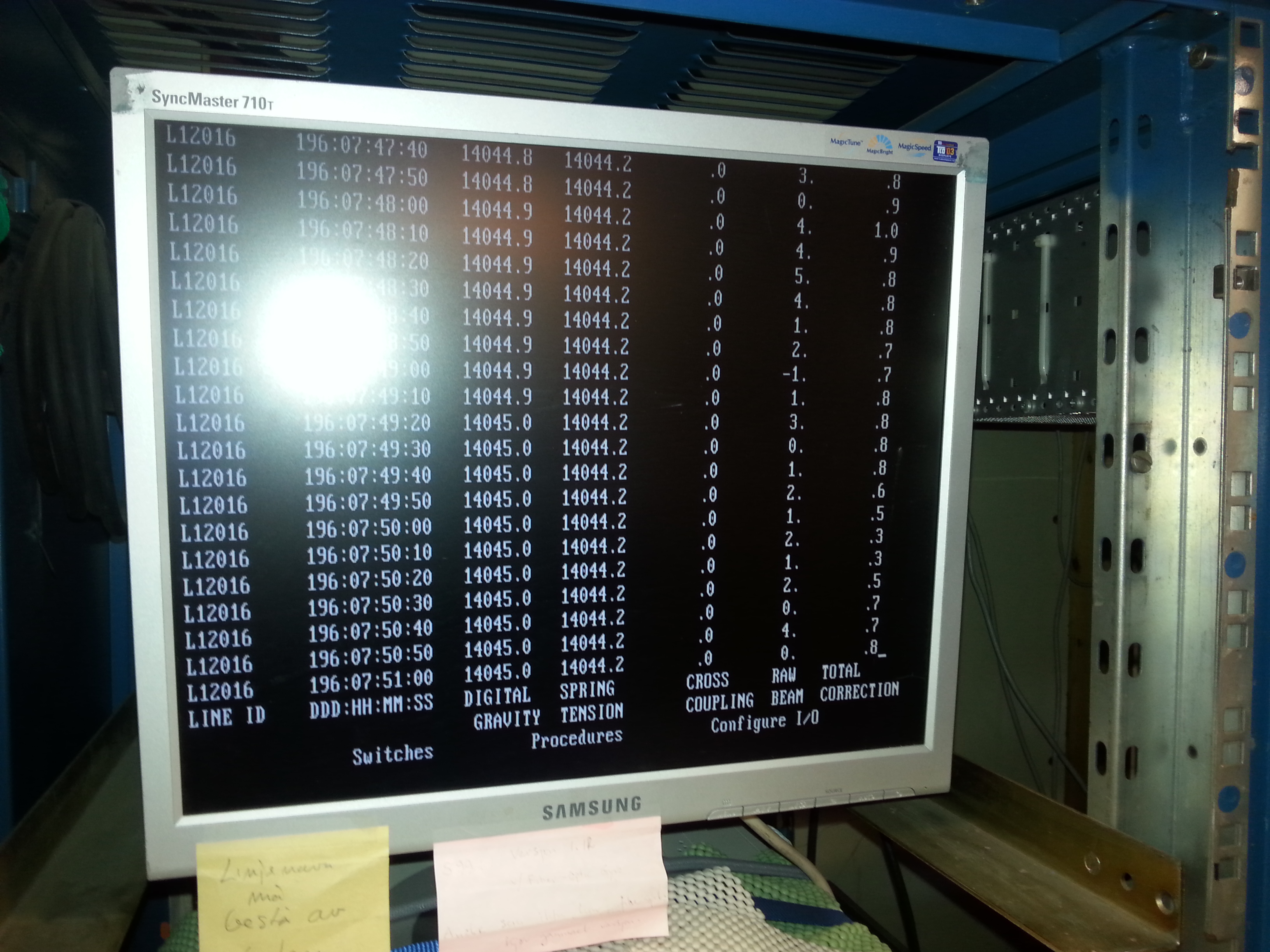
Raw gravity meter dataDirectory with raw gravity meter data (you will normally use georeferenced data in table above, with 10s logging interval). SCREENSHOTS
TO-DO
|
||||||||||||||||||||||||||||||||||||||||||||||||||||||||||||||||||||||||||||||||||||||||||||||||||||||||||||||||||||||||||||||||


