|
Past operations & data Scientific equipment
Communications / Navigation / Tracking
Weather Ship contact info VHF Radio Call Sign: Maintenance  Last update: December 27, 2024, at 09:41 AM |
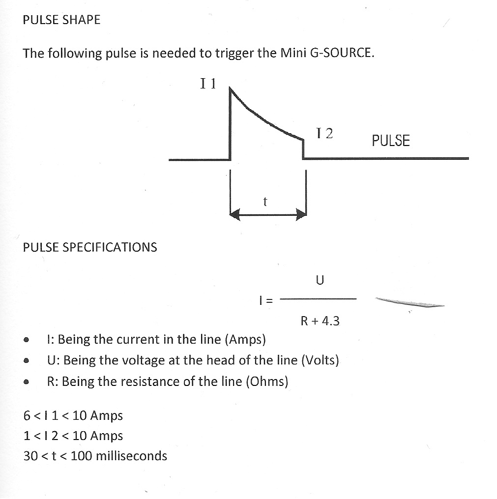
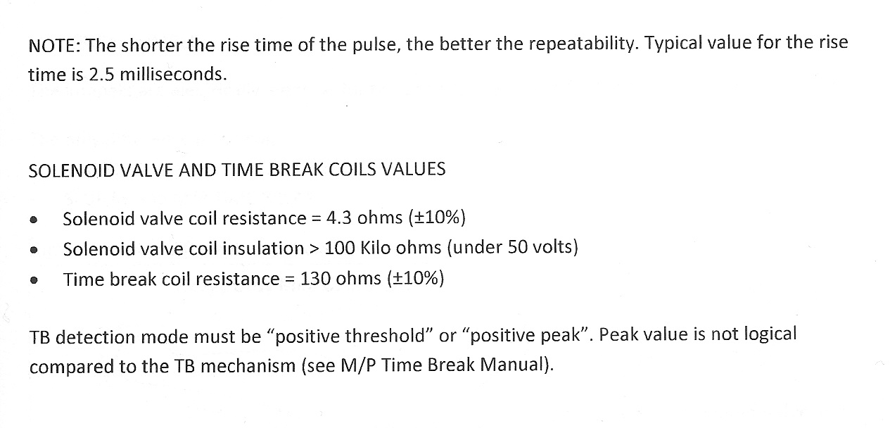
AIRGUN SOLENOID FIRING PULSE SPECIFICATIONSBolt airgun solenoidSercel Mini G-Source airgun solenoid
GUNCO HARDWAREOverviewThe Mini-GUNCO can be controlled through a computer serial port. COM port DTR & RTS lines are used to fire the airguns, according to this table: DTR -> GUN1 -> fire from 0 to 1 state RTS -> GUN2 -> ---"--- There is a wiring harness connection three units: PC, Mini-Gunco and GEODE. The aim is to fire airguns and trigger the seismic data collecting unit (GEODE) at the same time. A loopback between RS-232 RX and TX inside the Mini-Gunco permits auto-detection of GUNCO presence on a specific COM port. Refer to more detailed description here: http://www.geo.uib.no/eworkshop/GreenICE/#Instrumentation Trigger interface via RS232 port, using DTR (Airgun #1) and RTS (Airgun #2) signalsHardware (within the Mini-GUNCO)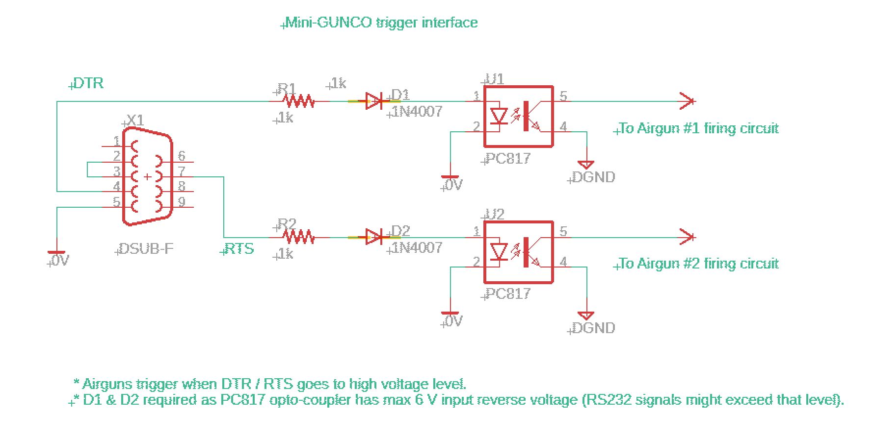 Software - Python example, using PySerial libraryThis is the GUNCO class of the program that controls firing of the Mini-GUNCO. Despite the two control signals being set (DTR and RTS, set to level=0) immediately after a GUNCO object is instanciated, voltage pulses are emitted on the DTR and RTS pins, causing the airguns to fire, if the airguns are left enabled by the master switches on the front. SO ENSURE THESE SWITCHES ARE IN THE "OFF" POSITION (=DOWN) BEFORE STARTING THE Mini-GUNCO PROGRAM. class c_gunco: def __init__(self, serial_port): self.Name = 'Mini-GUNCO' if serial_port: self.Serial_port = serial_port else: self.Serial_port = "COM4" self.Gun_number = 1 # 1 = Leftmost 2 = Rightmost slot position in Mini-Gunco self.SerialPort_handle = 0 #--- open serial port try: self.SerialPort_handle = serial.Serial(port=self.Serial_port, baudrate=9600, timeout=2) self.SerialPort_handle.setDTR(level=0) self.SerialPort_handle.setRTS(level=0) print "GUNCO object created, serial port =", self.Serial_port except: set_text_attr(FOREGROUND_RED | default_bg | FOREGROUND_INTENSITY) print "Could not open GUNCO serial port: %s" % self.Serial_port print "Check: Control Panel -> System -> Hardware -> Device Manager -> Ports (COM & LPT)" print "Quit" set_text_attr(default_colors) exit(-1) def fire(self, position, gun_number): if gun_number == 1: self.SerialPort_handle.setDTR(level=1) sleep(0.01) self.SerialPort_handle.setDTR(level=0) elif gun_number == 2: self.SerialPort_handle.setRTS(level=1) sleep(0.01) self.SerialPort_handle.setRTS(level=0) else: print "Invalid gun number (max = 2): %d" % gun_number #print " Gun number %d fired" % (gun_number) #print " %s:%s:%s UTC: GUNCO fired" % ( position.Hours, # position.Minutes, # position.Seconds) def close(self): #self.SerialPort_handle.close() pass def send_navdata_on_COM_port(self, data): self.SerialPort_handle.write(data.encode()) self.SerialPort_handle.flush() Wiring harness between PC-serial_port / Gunco / Geode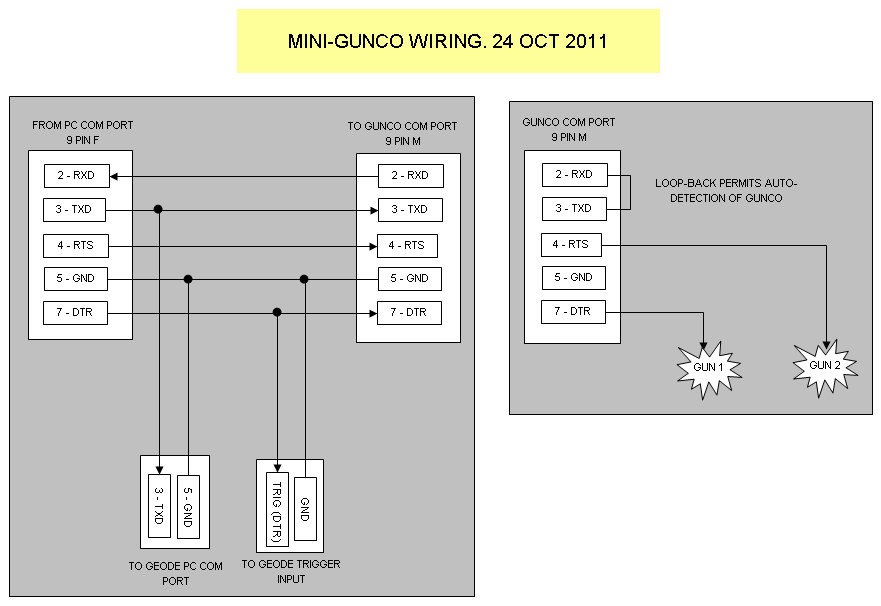 Mini-Gunco wiring. Wiring harness and part of mini-Gunco internal wiring shown. (mini-gunco-wiring-24Oct2011.xls) ModificationsList of changes, 2010The Mini-GUNCO was modified for 12 / 24 Vdc operation in May 2010.
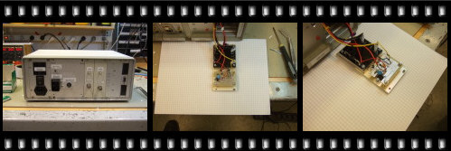 Modifications 2010, click to see images. List of changes, 2011
PROGRAMSoftwareNOTE: The Mini-GUNCO software depends on receiving regular GNSS/GPS data as UDP broadcast telegrams in a specific format (JSON), sent from another program running either on the same machine, or a different machine on the network. This emitter software is documented here: - GNSS/GPS data distribution software. Two different GNSS receivers have been tested:
Source code (in Python):
Screenshots
OBSOLETE - KEPT FOR REFERENCESoftwareCommand line options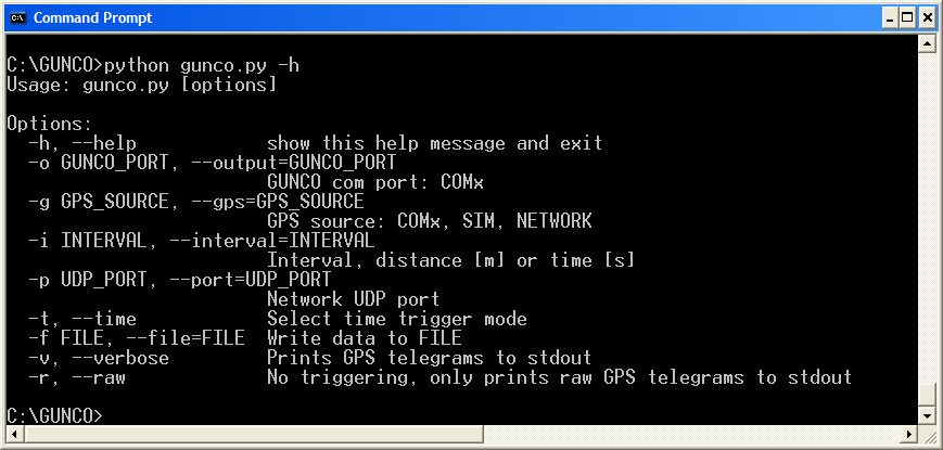 Normal mode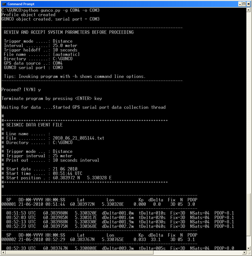 Debug (Verbose) mode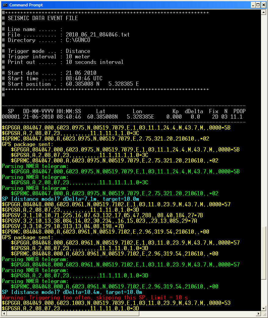 Raw data modeThe "raw data mode" is for debugging GPS serial input, and processing of these data. GPS telegrams used in the program is extracted from the GPS data stream and dumped to screen. In addition, the telegram package forwarded for further processing is displayed, and also processing of each element of the package. By "telegram package" we mean all telegrams associated with a given second. The system does not trigger the GUNCO in this mode. 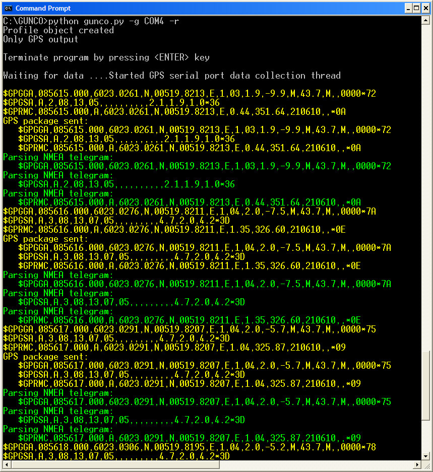 System in raw data mode. |
||||||||||||||||||||||||||||||||||