|
Marine gravitymeter, S-99
Land gravitymeter, G-936 Data format, conversion Air/Sea operation Base readings Data processing Projects Other information June 07, 2024, at 11:36 AM |
Power Supply & Platform Control Unit test pointsClick to see 2001 version. Click here to get a PDF version version of this document. You need at least a multimeter to perform these tests; an oscilloscope is, however, best. Power supply testThe power supply has three test points, phase A, B and C. These are the gyro spin motor excitation voltages. The motor is 3-phase AC, driven by 200 Hz sinusoids, 120º phase shifted. The phase voltages can be measured in two ways, a) Neutral (0V) to Line, or b) Line to Line. Phase voltageUsing multimeter: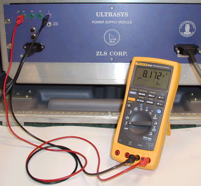 Meter setup: AC. Measure between 0V and each phase, and between phases. Also measure frequency, if the multimeter has this capability.
TBD = To be determined. Using oscilloscope: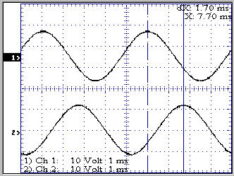 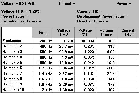 Data from Tektronic oscilloscope TDS210. Calculated by Tektronix's WaveStar software. Measure between 0V and each phase. Note: Do not measure between phases by attaching the probe's ground clip to one of the phases - you risk making a short circuit if the scope's ground is tied to power supply 0 V. Instead make a differential measurement using two probes, ground clips to 0V, and then subtract ch.2 from ch.1. The figure on the right shows phase A and B. Peak-to-peak value is approx 24 V. The phase difference can be measured to (1.7ms/5ms)*360º = 122º; the cursor readout is however not very accurate, so this just indicates the 120º phase shift. The signals are not "pure" 200 Hz sinusoids. If a spectral decomposition (FFT) is performed the harmonic distortion can be measured. The amplitude of the 3rd harmonic (600 Hz) should be less then 1% of the fundamental (200 Hz). It was measured to 1.2% (refer to figure on the right). Platform control unit tests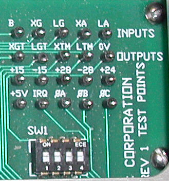 The test points are located on a small printed circuit board inside the Platform Control Unit, below the metal lid - see the figure to the right.. Learn the "nomenclature" - it makes testing easier: X = Cross L = Long G = Gyro A = Accelerometer T = Torque M = Motor Note that "torque" applies to two components: a) The motors that keep the platform level, and b) the gyros, where the torque input signal is used to compensate for long-term horizontal reference changes (e.g. earth rotation). If you're not aware of this it can be a bit confusing. Program switches SPRING TENSION and ALARM set to OFF.
DC voltages ±28V, ±15, +24V, +5V can also be checked via UltraSys program. Misc |