|
Past operations & data Scientific equipment
Communications / Navigation / Tracking
Weather Ship contact info VHF Radio Call Sign: Maintenance  Last update: December 27, 2024, at 09:41 AM |
EVALUATION OF NAL RESEARCH MOD. 9601-DGS-LP
INTRODUCTIONThis brief report documents evaluation of the NAL Research Mod. 9601-DGS-LP Iridium/GPS Tracking device. Figures and information from NAL Research General Description of Model 9601-DGS-LP - Technical Note 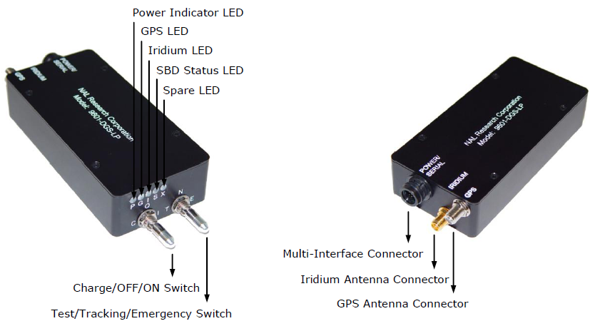 The NAL mod. 9601-DGS-LP tracking device. Firmware versionFirmware version is 1.2.2. Antenna, dual Iridium + GPS
DocumentationManufacturer recommends the following documentation reading order. They are available from manufacturers ftp server.
We currently use the tracker in stand-alone, automatic mode (we do not feed it with custom information through the units RS232 interface), so item 3 can be skipped for now. As we receive SBD telegrams as emails, the last two items can also be omitted.
SBD SERVICEWe have ordered a SBD (Short Burst Data) service for the 9601-DGS-LP. Each SBD telegram will be forwarded as email to mail accounts we specify. It is a fixed-cost plan under these terms:
We have to clarify what is meant by "Mail box check: $0.02/message" as we do not POP (read) emails from an Iridium mailserver - instead emails are sent to accounts we specify. They probably mean cost per email sent. Each SBD message - sending Latitude, Longitude and CEP (Circular Error Probability) radius - will use approx. 25 bytes, like this example shows: 60.364306 005.299438 4
Cost of hourly reportAssuming we send 25 bytes per SBD telegram, hourly position report will will amount to: 25bytes/message * 24messages/day * 30days = 18,000 bytes per month
Subtracting 12,000 free bytes cost will be: 6,000 bytes * USD 0.0015 per byte = USD 9 per month, in addition to USD 16 fixed cost, in total USD 25/month
Cost of report every 30 minuteRecalculating for report every 30 minutes yields: "Byte cost" USD 36. Adding fixed cost USD 16 gives USD 52/month
MULTI-INTERFACE CONNECTORInterface is through a Hirose 12-pin connector model HR30-7R-12P with corresponding mating connector model HR30-7P-12S.  Hirose HR30-7P-12S cable connector.
Pin-out is as follows: 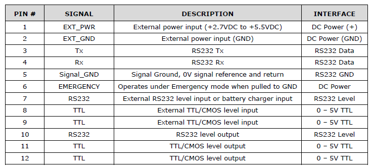 Pin-out on multi-interface connector, mod. 9601-DGS-LP The cable connector has this pin numbering - viewed from the wiring side: 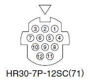 Pin numbering, seen from wiring side, of cable connector Hirose HR30-7P-12SC. Interface cable: Pin 1 -- RED -- EXT_PWR -- External power input (+2.7VDC to +5.5VDC) Pin 2 -- BLACK -- EXT_GND -- External power input (GND) Pin 3 -- YELLOW -- Tx -- RS232 Tx (data to mod. 9601-DGS-LP) Pin 4 -- BLUE -- Rx -- RS232 Rx (data from mod. 9601-DGS-LP) Pin 5 -- GREEN -- Signal_GND -- Signal Ground, 0V signal reference and return Pin 6 -- WHITE -- EMERGENCY -- Operates under Emergency mode when pulled to GND
POWER SUPPLY REQUIREMENTSSpecifications: Main Input Voltage Range: +2.7VDC to +5.5VDC
Main Input Voltage Nominal: +4.0VDC
Main Input Voltage Ripple: 40mV peak-to-peak
Peak Current: 1.5A @ 4.0VDC
Power consumption during standby: Less than 20 uA
Power Input Type: External DC power or internal battery
Quoting from p. 2 of Getting Started with Model 9601-DGS-LP (TN2008-850-V1.0): ... input ranging from 2.7VDC and 5.5VDC to the Hirose connector via pins 1 (+) and 2 (GND). The cable should be kept as short as possible to prevent significant voltage drop, which can cause the 9601-DGS-LP to malfunction during an SBD session. Power reset by the 9601-DGS-LP during an SBD transmission is an indicative of the DC power source unable to sustain voltage above 2.7VDC at peak current demand.
We used a thin multiconductor cable for the Hirose multi-interface connector; each conductor wire was 0.055 mm2. DC/DC-converter12 Vdc is available on the hovercraft. Nominal supply for the NAL Iridium tracker is 4.0 Vdc. So we need a voltage regulator that satisfies the stringent requirements of the tracker. We first made a LM317 type linear regulator, but were still plagued by power reset when the Iridium transmitted started to send SBD telegrams. So we decided to purchase the DC/DC-converter that NAL Research manufacturers - Model SYN-DC-936UK.  NAL Research Model SYN-DC-936UK DC/DC converter. Input Connector
Output Connector
[Note - there seems to be a mismatch between power supply requirements of the tracker, in particular maximum input voltage ripple allowed (40 mV peak-to-peak {no bandwidth specified}), and corresponding specification of the DC/DC converter (ref output specifications p.2 in General Description, noise {bandwidth: 0.01 - 1 MHz} 100 mV peak-to-peak, and {bandwidth: 0 - 20 MHz} 150 mV peak-to-peak.] Cable assemblies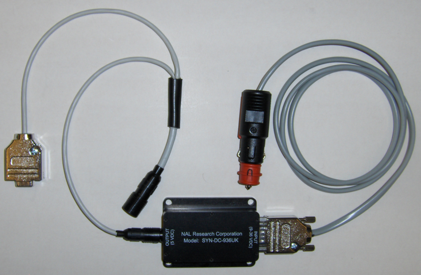 The Hirose connecters are miniature. It was very difficult to solder wires of a multi-conductor cable. Instead, we used individual 0.22 mm2 wires and inserted them into outer sheathing (grey on image). Also used 1.5/0.5 heat-shrink tubing over solder terminals. On 9-pin D-sub (solder type) we used a sturdy metal shell (supplier ELFA P/N: 44-110-13). Car-12Vdc connector supplier: Farnell, P/N: 658364.
CONFIGURATIONUsing the SatTerm software provided by the manufacturer, the unit is configured from this window: 18 August 2009: Configuration of Mod. 9601-DGS-LP using manufacturer's SatTerm program. Dump of SBD session: AT+SBDWT=Test 18 aug 2009 OK AT+PSIX +6023.062,+00519.787 +SBDIX: 18, 7, 2, 0, 0, 0 OK AT+PSIX +6023.062,+00519.786 +SBDIX: 0, 7, 0, 0, 0, 0 OK AT+SBDWT=Test #2 18 Aug 2009 OK AT+PSIX +6023.060,+00519.793 +SBDIX: 32, 8, 2, 0, 0, 0 OK AT+SBDWT=Test #3 18 Aug 2009 OK AT+PSIX +6023.057,+00519.799 +SBDIX: 0, 8, 0, 0, 0, 0 OK
RELATED HARDWARE Antennas: SYN7391 Series, SAF2040 Series, SAF5340 Series, SAF5350 Series, SAF7352-IG and SAF5270-G
AC Power Adapter: LA-3098 (100 - 240VAC, 47 - 60Hz input)
Car Adapter: LA-7021 (12VDC car battery input)
DC-DC Converter: SYN-DC-936UK (9 - 36VDC input)
Power Cable: HRC-24-9, HRC-24-9A, HRC-24-10 and HRC-24-10A
Battery Pack: SYN-LI-2AH, SYN-nLI-2AH
|