|
Surveys and data Instruments
Support to other department sections Support Dr. Scient. thesis Contribution to "Scientific infrastructure"
Obsolete, kept for reference
Last update: April 30, 2025, at 08:49 AM |
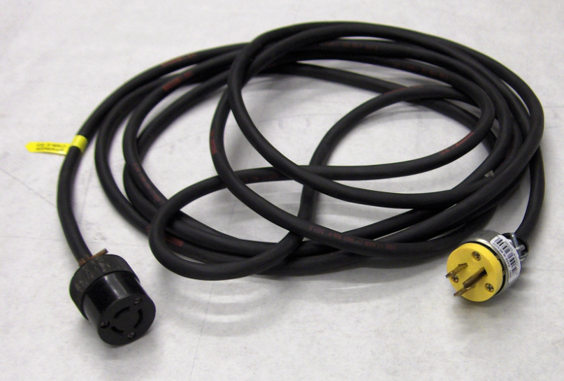
EG&G SPARKER SYSTEM (discontinued)A sparker system comprises an impulsive energy source and a projector which emits acoustic energy, being towed behind the survey vessel. The projector can be a sparker which generates acoustic energy by discharging a high voltage pulse between electrodes, vaporizing water and thus generating a bubble which subsequently collapses, in a small volume around the electrodes, or a boomer which emits an acoustic pulse by rapid movement of a mechanical assembly when a large current is injected into a coil. So, technically, "sparker" denotes the electrodes being towed behind the survey vessel, and the power supply is a more general component that can feed different types of projectors - both sparkers and boomers - but we will use the expression "Sparker system" to mean geophysical instrumentation of this kind. 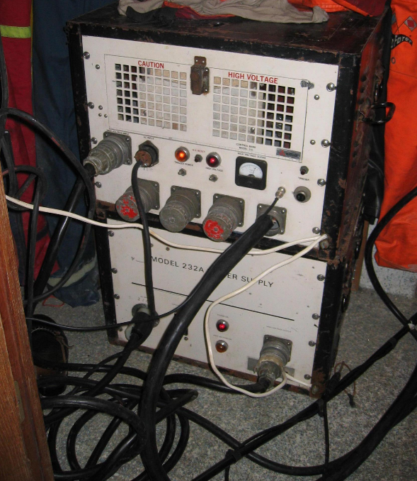 EG&G mod. 232A "Power Supply" and mod. 231 "Triggered Capacitor Bank". TRIGGERINGThe control unit is furnished with BNC input connector for triggering the system. A positive pulse is required. Refer to User manual for exact specifications. ENERGY LEVEL SELECTION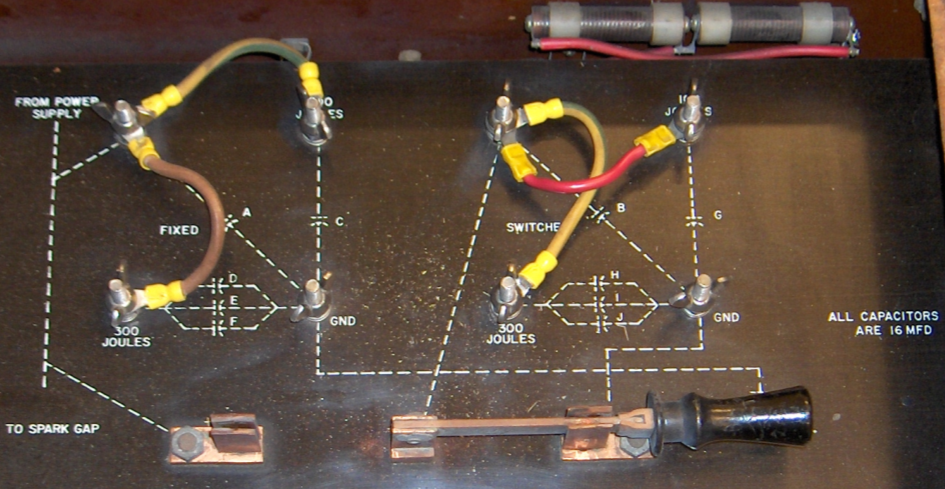 Energy selection, 100 - 1000 Joule, in steps of 100 Joule. Photo shows 500 Joule operation. The wiring diagram that is etched into the metal surface shows a system of capacitors wired in parallel. Each capacitor symbol represents 16 mF yielding 100 Joule energy with the high-voltage level that is applied. The wiring straps now divide the capacitance (expressed as energy - in Joules) into two sections. The one to the left is 300 + 100 + 100 Joule = 500 Joule. The section to the right also represents 500 Joules. The large switch will either short-circuit the section to the right, or include it in operation. As shown, the right capacitor section is short-circuited. This layout provides a high degree of flexibility when energy level is selected: 100 - 1000 Joule, in steps of 100 Joule. SPARK GAP CLEANINGYou might need to clean spark gap terminals: 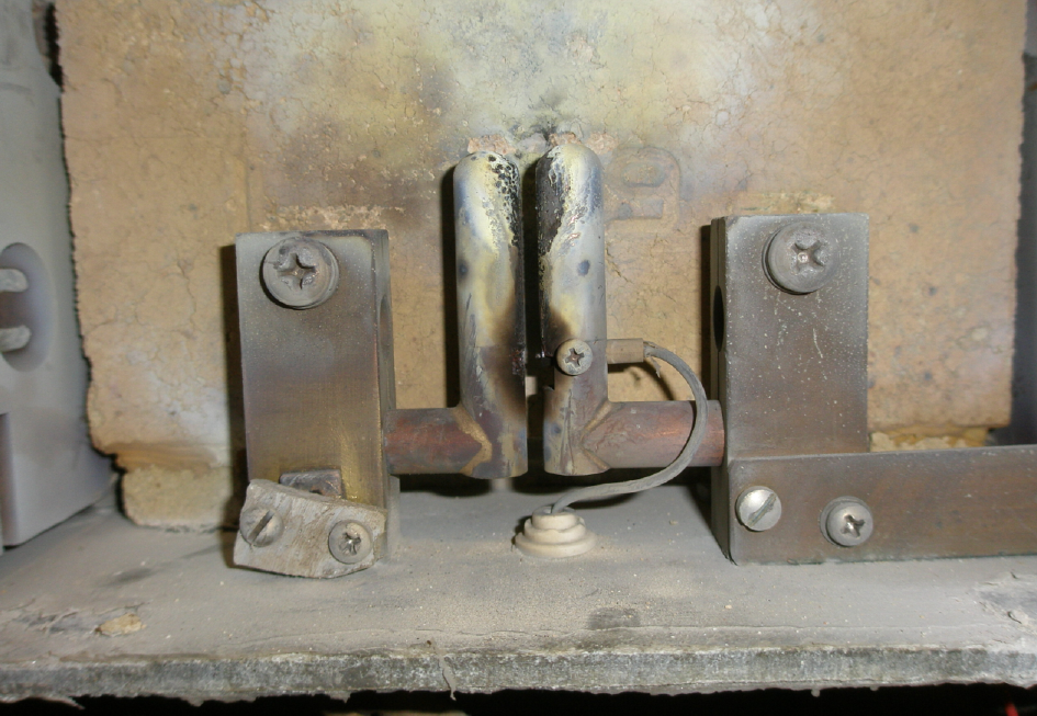 The spark gap terminals may need cleaning. Use abrasive paper sheets. CONNECTING THE DECK CABLE TO ENERGY SOURCE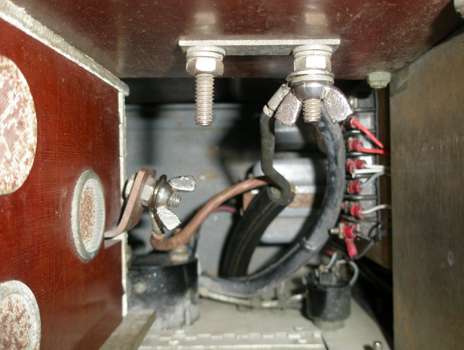 Connection of sparker. No polarity on sparker; on boomer connect "brown" wire to left terminal. The sparker element has no polarity. For the record: Boomer plate HAS polarity. Brown wire should go to Sparker Control Bank "positive" terminal (left on picture below). Boomer plates will move in opposite direction (which is not desirable) if polarity is not correct. TYPICAL INSTRUMENTATION CONFIGURATIONA complete seismic acquisition system must comprise source, receiver, recording (or plotter) and interface to ship's navigation system. Here's a typical setup, used on the GEOL-110 course in 2008.
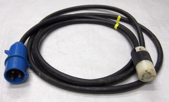
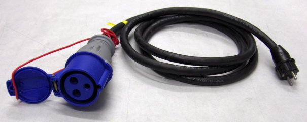
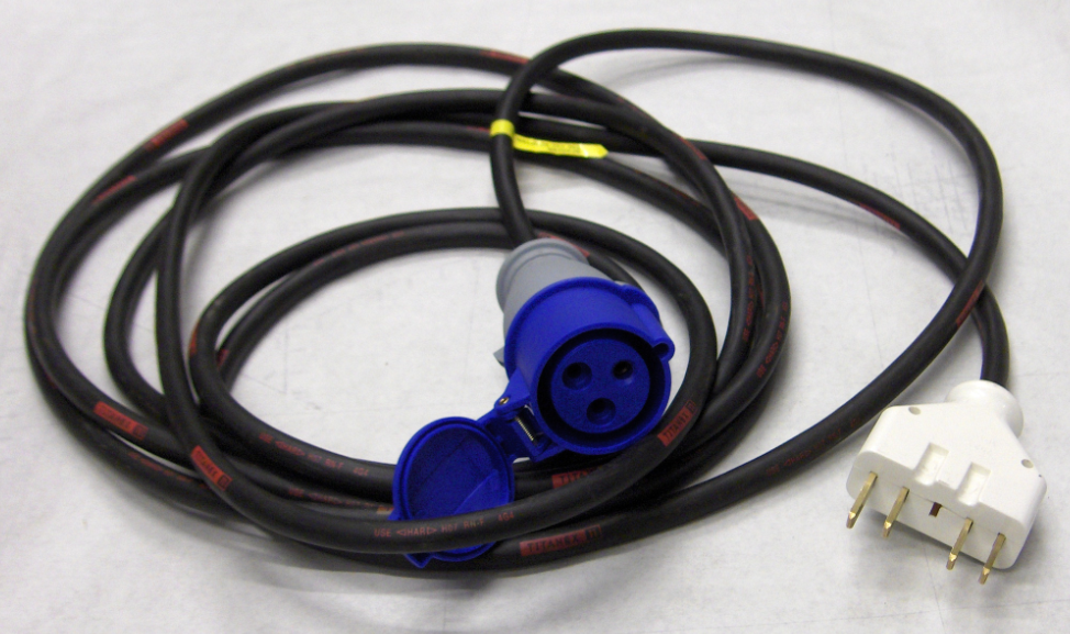
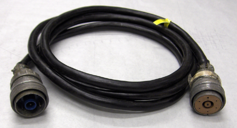
Instrumentation diagram, GEOL-110, February 2008 Cables used during GEOL-110 field course, February 2008
|
||||||||||||||||