|
Surveys and data Instruments
Support to other department sections Support Dr. Scient. thesis Contribution to "Scientific infrastructure"
Obsolete, kept for reference
Last update: April 30, 2025, at 08:49 AM |
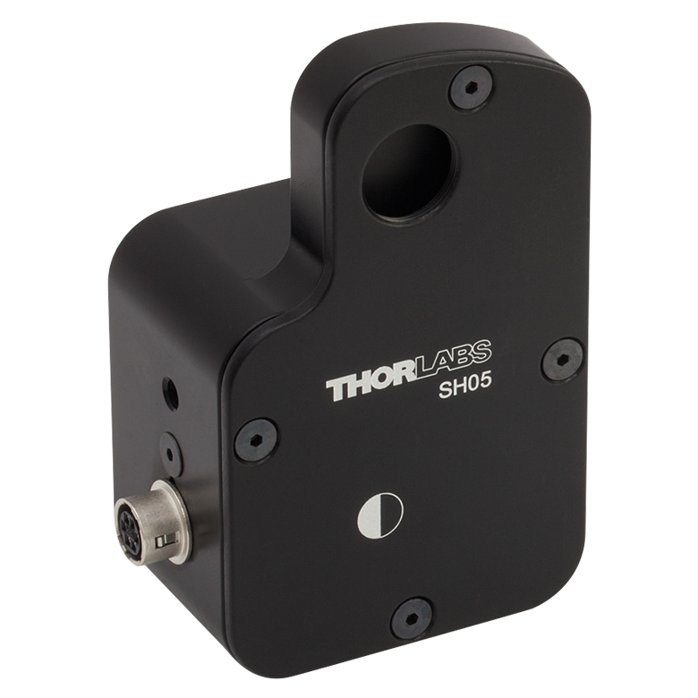
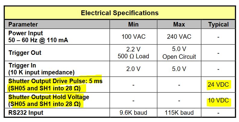
TABLE OF CONTENTSBACKGROUNDThere is a problem with a tailor-made shutter control unit: At least one of the four shutters that can be connected, does not work properly. We are sure there is nothing wrong with shutter units as all work normally when attached directly to KSC101 "K-Cube Solenoid Controller". INSTRUMENTATIONShutter Unit: ThorLabs mod. SH5 Optical Beam Shutter
Newer units
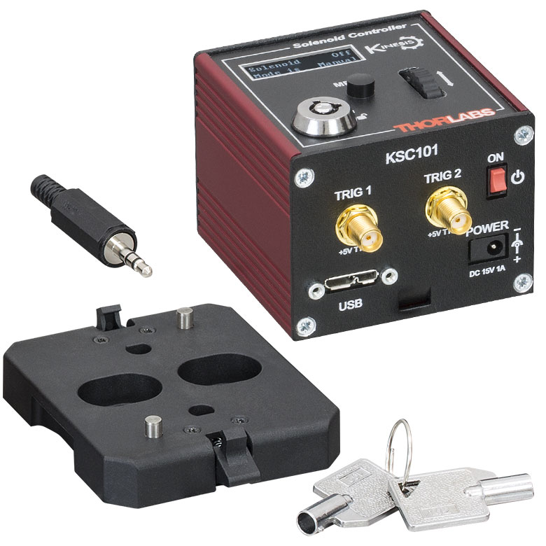
Shutter Controller ThorLabs mod. KSC101 "K-Cube Solenoid Controller"
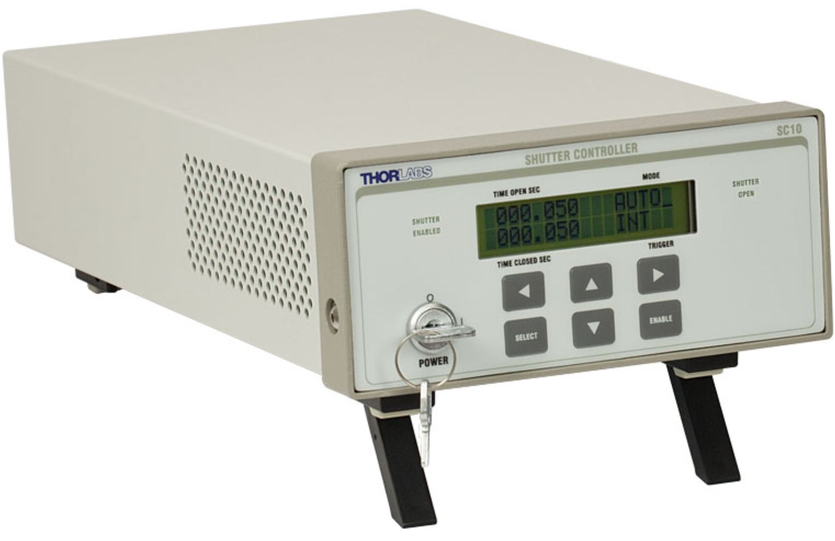
Shutter Controller: ThorLabs mod SC10 - Optical Beam Shutter Controller
INVESTIGATION: SHUTTER SOLENOID CONTROL WAVEFORMSSH5 Optical Beam Shutter driven directly by KSC101 "K-Cube Solenoid Controller" in manual mode.
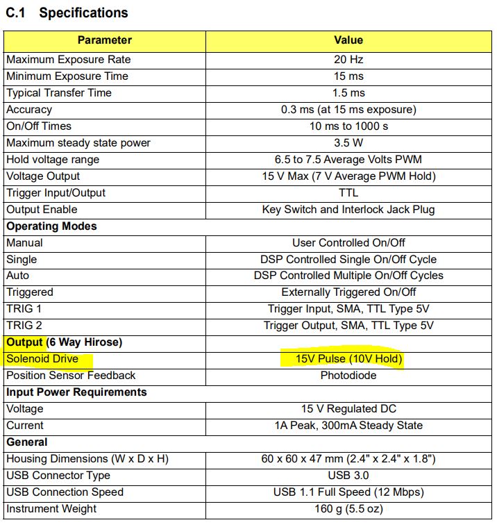
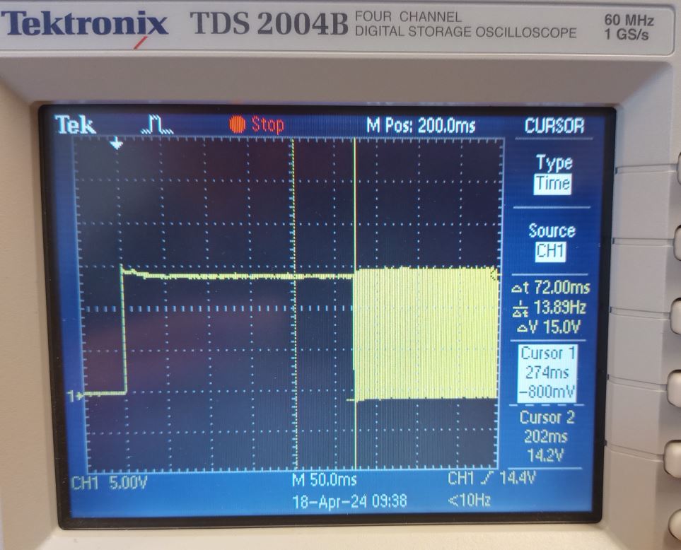 Fig A: SH5 Optical Beam Shutter driven directly by KSC101. Shutter controlled by scroll wheel. 15 V applied to SH5 solenoid, and after 275 ms the control signal changes to square wave with duty cycle so RMS value becomes 10.0 V (fig C) -- spot on according to KSC101 specifications (see above) ...! 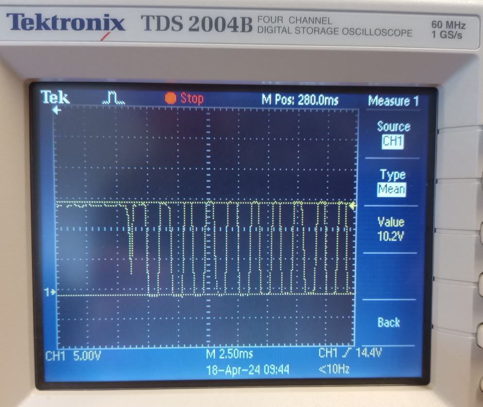 Fig B: SH5 Optical Beam Shutter driven directly by KSC101. Details of onset of square wave section of control signal. Disregard the "10.2 V mean voltage reading, which is a result of the complete, composite waveform. Fig C shows RMS value of the square wave section itself. 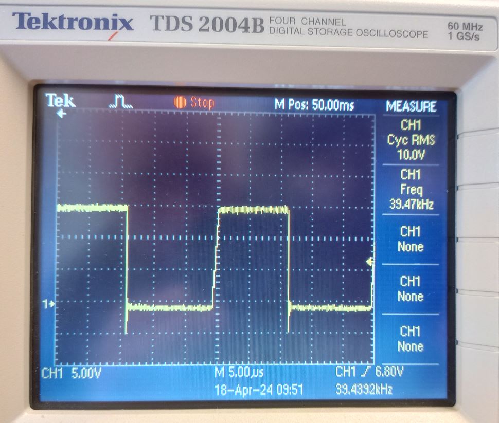 Fig C: SH5 Optical Beam Shutter driven directly by KSC101. One cycle of square wave portion of solenoid control signal. RMS value: 10.0 V -- correct according to KSC101 specifications. SH5 Optical Beam Shutter driven by GEO Fluid Inclusion Lab control unit
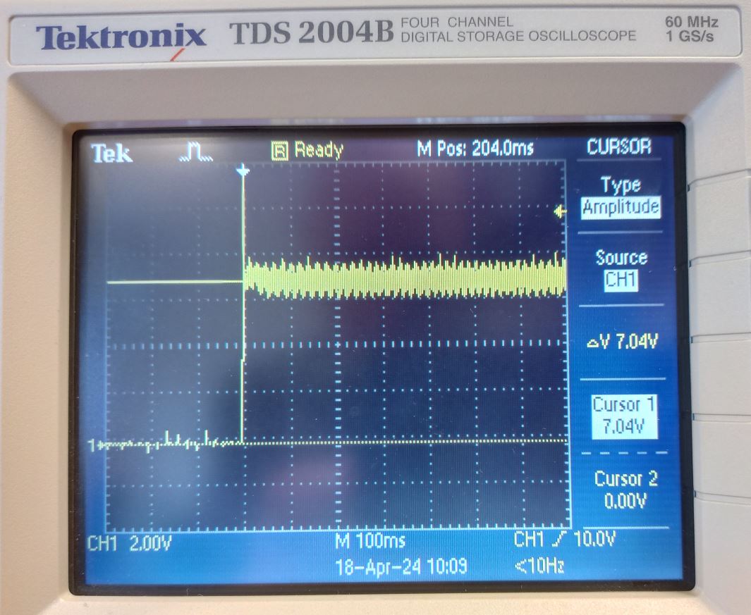 Fig D: SH5 Optical Beam Shutter driven by GEO Fluid Inclusion Lab control unit. 7 V applied to SH5 solenoid. Signal ON waveform is constant over tide. 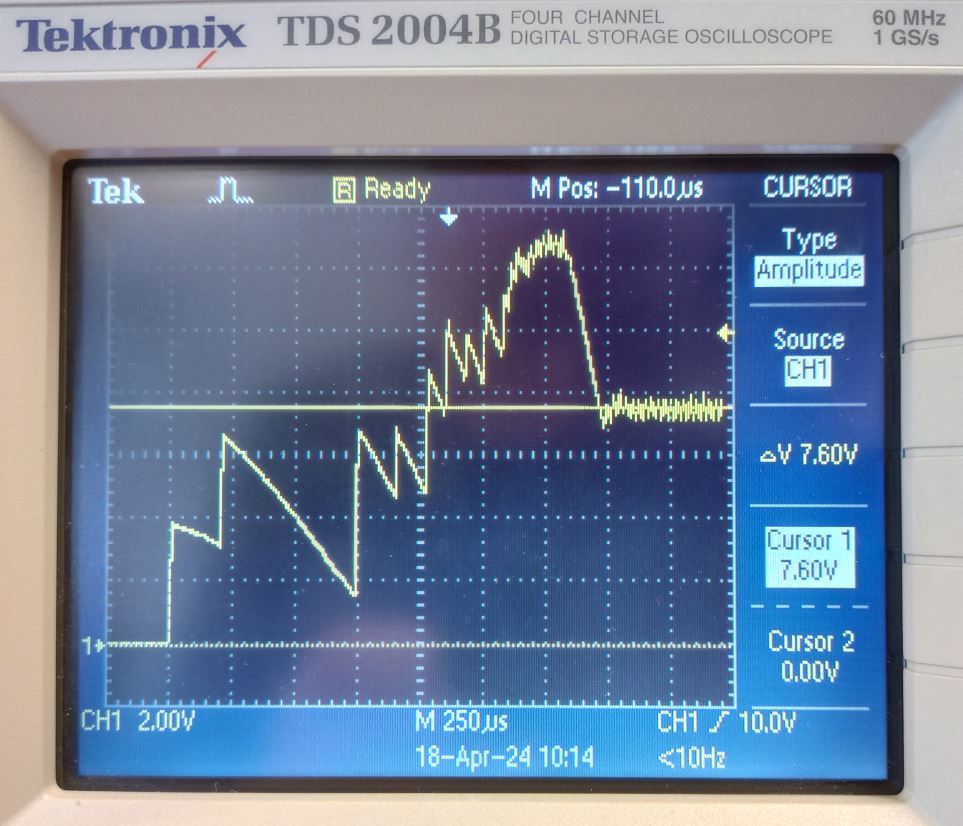 Fig E: SH5 Optical Beam Shutter driven by GEO Fluid Inclusion Lab control unit. Start of SH5 solenoid control signal. Initial transients probably casued by relay mechanical effects. Test setup Fig F: Test setup. Click to enlarge.  Fig G: Oscilloscope probe attached to SH5 solenoid control wires. Click to enlarge. DRIVER / SYNCHRONIZING UNIT, TAILOR-MADE - DOCUMENTATION --- Not complete
|
|||||||||||||||||||||||||||||||||||||||||||||||||||||||||