
|
Surveys and data Instruments
Support to other department sections Support Dr. Scient. thesis Contribution to "Scientific infrastructure"
Obsolete, kept for reference
Last update: April 30, 2025, at 08:49 AM |
MARINE STREAMERSMINI-STREAMER, 8 CHANNELS (2011)Click image to enlarge:  8-channel mini-streamer. Click to enlarge. Specifications Lead-in ..................: 150.00 m
Active section: 8*6.25m ..: 50.00 m
Tail .....................: 12.50 m
--------
Total length ..: 212.50 m
-------------------------
Deck cable length: 27 m
Cable diameter, lead-in: 14 mm
Cable diameter, tail: 32 mm
Power consumptionThe streamer is powered by Geometrics DHA-7 Battery Pack, P/N: 0060165-01. It consists of two 5 Amp-hour batteries. Each hydrophone preamplifier draws approximately ±10.8 mA per channel. An 8-channel streamer can be powered continuously for approximately 58 hours (5 Amp-hours divided by 86.4 mA (10.8ma *8 channels)).
Streamer geometry requirements
Recording system specifications
This is a voltage input amplifier. A charge amplifier is normally used with the Mini-Streamer. This is a low-impedance, current input type amplifier, with a fairly low output impedance (suitable for connection to e.g. GEODE and similar types of seismographs).
Seismic source - typicalPrimary useThe Mini-Streamer will most often be used as a supplement during Ocean Bottom Surveys. In this type of survey, the recording instruments are first put on a gridded line on the ocean bottom. Then the ship turns and fires the seismic energy source over the same line. Operating with offsets (distance between source and first recorder) of tens of kilometers, sometimes several hundred kilometers, the source must be able to output low-frequency, high amplitude signals. In practice, several high-volume airguns are used. The acoustic signal shape of this source is not ideal for the Mini-Streamer, but as a supplementary data acquisition system we just have to make do ...
Secondary useShallow seismics, using sparker as source.
Reel for mini-streamer
DIGITAL, 240 CH, 3 KM (2001)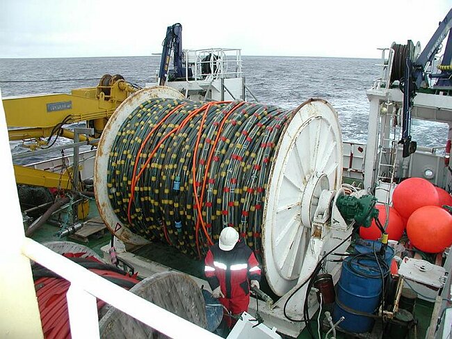 Nessie-3, RV "Håkon Mosby" September 2001
Nessie-3 (N3) main features
N3 structureA streamer is composed of several different pieces - stretches, active sections, bubbles, repeater bubbles, tail-buoy tow cable. Every second active section is followed by a bubble. Hydrophone groups overlap between sections, hence, at the front of the actives we use a 10m half group section (the last active at the tail has a redundant half group). 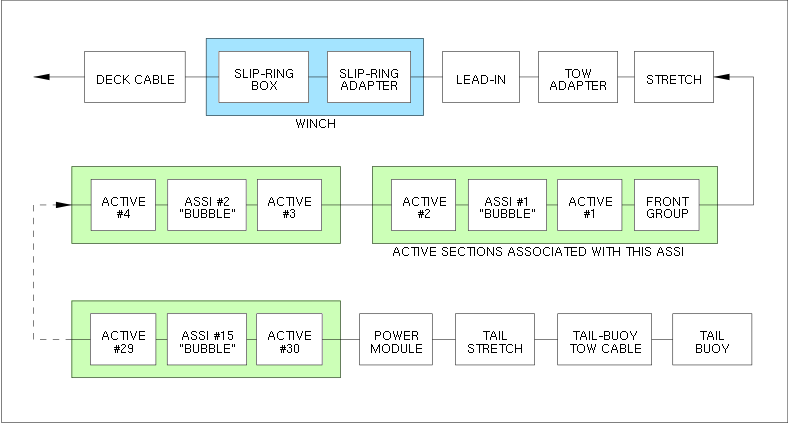
Streamer section nomenclatureAll Western-Geco streamer sections have their own unique identification code and serial number. The code consists of letters, and indicates the function and hardware arrangement of the section. 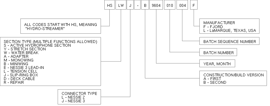 Western-Geco Nessie-3 streamer section nomenclature Recording system
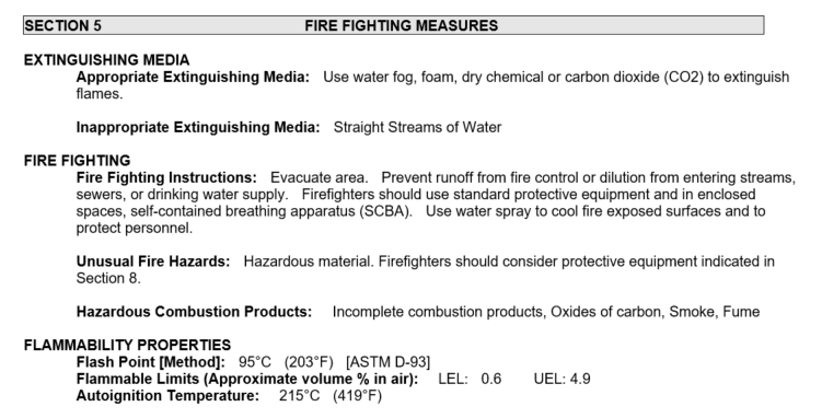
Streamer maintenance, 2009In the spring of 2009 a major maintenance program was implemented. Several streamer sections were scrapped and replaced by spare sections. Streamer map, 30 August 2012Hakon_MosbyN3_Svalex30aug2012.xls For reference: N3_Resultat_verUiB_25mai2009-new-map.xls Streamer Oil: ISOPAR M "Safety Data Sheet" EXXON ISOPAR M "Safety Data Sheet":
Link to "Safety Data Sheet"
Source of "Safety Data Sheet":
http://www.msds.exxonmobil.com/IntApps/psims/psims.aspx
"Country Of Use", select: USA
"Product / Trade Name", enter: ISOPAR M
With reference to:
Schlumberger Doc. no.: D20010216
"Operations Manual - Digital Hydrostreamer Nessie 3 & 4"
Issue 9, Dated: March 1997
Section 4.3 "Oil filling - Control of Kerosene"
"The latest skin type with ribs inside (58,5 x 3,5) have a volume of approx. 200 liters (N3-B), [...] and the 50m stretches should be filled with approx 130 liters."
Quantity of ISOPAR-M oil in UiB 3 km streamer:
2 ea Stretch sections (front + tail) ...: 130 liter x 2 ea = 260 liter
30 ea Active sections ...................: 200 liter x 30 ea = 6000 liter
------------------------------------------------------------------------------
Liter in streamer, on winch ......: 6260 liter
------------------------------------------------
Extra: Barrel of oil, for filling-up sections that need it .........: 209 liter
---------
 Winch for N3 streamer - dimensions29 May 2017, measured on winch, in Longyearbyen (storage facility, contact LNS Spitsbergen): Frame is 3,92 x 2,45 m, drum approx Ø 3m, hydraulic motor protrudes 0,95 m from drum, and distance from center of hydraulic motor to ground is 1,55 m.
ANALOG STREAMER, 120 CH. 3000 M (1996)NOTE: Certain parts of the analog streamer system has been phased out. Information is kept as a reference. 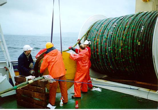 Analog marine seismic streamer, 120 ch., 3 km, on board RV "Håkon Mosby" (1996).
System diagramA block diagram of the analog streamer instrumentation system is shown below:  Keeping vertical positionIn order to control streamer depth, it it furnished with depth control devices at regular intervals. These devices have two horizontal fins whose angle of attack relative to the water flow can be varied. This creates vertical forces - much like the elevators on an airplane. The depth control units, called "Birds", number eight in total. They are clamped on to the streamer at regular intervals during streamer deployment. After being remotely programmed to keep a certain depth they act autonomously. By altering the fin angle the bird seeks to reduce any deviation from the set target depth, continuously being questioned by the Bird Controller System to report the result of its efforts We are using Mod. 5010 DigiBIRD, manufactured by DigiCOURSE (later aquired by INPUT/OUTPUT, INC.). The Kalamos Fault LocatorThe danger of seawater intrusion, either into streamer connectors or into the streamer body, is always present. Seawater acts as an electrical conductor. It may cause shorts or electrical leakage between conductor pairs, or across pairs. The Kalamos Fault Locator is an aid in pinpointing the exact leakage location. The Kalamos is still in use. Time sequence The sequence of events taking place during recording of streamer data is shown below. Time is on the vertical axis. Hydrophone group configurationDiagram for 12,5 m group:  Data for 12,5 m group:
25 m group consists of two 12,5 m groups wired in parallel:  Data for 25 m group:
Technical informationEqualizerIn an analogue streamer the hydrophone (sensor) signals are transmitted through twisted wire pairs in the streamer to the instrumentation system. These wire pairs deteriorate the signal due to distributed capacitance and resistance along the way. The signals coming from the far end of the streamer will, of course, suffer most. The role of the equalizer is to make all streamer channels appear equally 'bad', seen from the subsequent element of the instrumentation chain. It does so by inserting a resistor-capacitor network into the signal path of every channel, simulating a certain length of a twisted wire. The nearest hydrophones will have the largest equalization. The resistor-capacitor values will then gradually decrease until there seems to be an equal distance of twisted pair wire between every hydrophone in the streamer and the subsequent signal processing equipment.  Equalizer circuit diagram (one channel). Charge amplifier model DSS VModel: DSS V - CHARGE AMPLIFIER SYSTEM Assuming group length is 25 m, we have the following parameter values:
Sensitivity calculation: For a differential charge amp with equal feedback capacitors (as DSS is furnished with), we have the following gain expression: 
Where: SO1=Sensitivity [Volt/Bar] after charge amp.
CG=Group capacitance [nF]
CF = Differential charge amp. feedback capacitance values [nF]
SG = Group sensitivity [Volt/Bar]
There are three versions of the DSS "Signal Conditioner Card" (SCC), each with different feedback capacitors values: P/N: 500-052-03 : CF = 70.0 nF
P/N: 500-052-05 : CF = 47.0 nF
P/N: 500-052-11 : CF = 100.0 nF
We are using dash 03 SCC. Thus: 

The output signal from the differential charge amp is routed to the Mode Control section, as shown below. Various signal amplitudes are made available to the multiplexer (MUX) Z3 by the resistor pack A5 acting as a voltage divider. MUX signal lines A, B and C determines which amplitude is selected, and these lines are set by the Mode Control plug. 
There are different Resistor Packs depending on streamer type and group lengths. We are using Resistor Pack mark 113-0003-027, manufactured by Seismic Engineering Company. They have the following measured resistance values: R1 = 15,718 kohm
R2 = 0 ohm
R3 = 10,721 kohm
R4 = 3,556 kohm
R5 = 1,779 kohm
R6 = 1,073 kohm
R7 = 714 ohm
R8 = 3,568 kohm
Normally the values of resistors R1 to R8 are chosen so that:
With 25 meter group length charge amp sensitivity is 174,86 V/Bar. If MUX Z3 input no. 2 is selected the sensitivity becomes: 


Two problems will arise:
If Mode Control plug of type 1-1-0 is used the sensitivity of the corresponding MUX input (no. 4) will be: 

The consequence is that the sensitivity selection switch on the instrument front panel (labelled "System Output [Microvolt/Microbar]" on the DSS System Control unit) will have different values then those stated. The front-panel sensitivity figures must be divided by two. Charge amplifier model CHAMPWe also have a 56 channel charge amplifier system manufactured by Fjord Instruments (a division of Western-Geco). The system has been used with sections of the analog streamer.
STREAMER DEPTH CONTROLS UNITS - "BIRDS"These units are mounted externally on a marine seismic streamer cable. The streamer is furnished with a set of collars at regular intervals where the vertical control unit (called "Birds") are mounted while the streamer is deployed. We have been using DigiBirds manufactured by ION.
Data sheets, documentation
Streamer collars
  31 July 2009:
  To: Earl Smith <esmith _at_ oyogeospace.com>:

  PURCHASE ORDER
  --------------
  With reference to quotation (see below) we wish to order:

  --------------------------------------------------------------------------
  Pos  Qty  Unit  P/N             Description
  --------------------------------------------------------------------------
   1   (10)  ea    07-526280-260   Bird collar, standard length, $24.50 each
   2   (10)  ea    07-526281-260   Bird collar, extended length, $29.50 each

  Hi,

  Please quote price and delivery time for:

  10 sets of streamer Bird collars, inner diameter 2.6 inch (both large and small).

  The large collar - 4.4 inch long - has these marks:
        JRC CONCORD TECH, INC   PN 07-526280-260
  The small one - 3.4 inch long - has identical PN:
        07-526280-260
Repair of Digibirds
|

