
|
Surveys and data Instruments
Support to other department sections Support Dr. Scient. thesis Contribution to "Scientific infrastructure"
Obsolete, kept for reference
Last update: April 30, 2025, at 08:49 AM |
Instrumentrom med TriAcq og Geco GUNCO, FF Håkon Mosby, SVALEX-2011. Klikk for større bilde. Link til SVALEX-2011 fotoalbum.
LAGRINGSBEHOV VED FORSENDELSE AV INSTRUMENTERING, FØRSTE DEL
OVERSIKT: DELER SOM TRIACQ SYSTEMET BESTÅR AVNessie-3 (N3) streamer
TriAcq recording
Fra før hadde UiB andre deler som trengtes:
Systemet skal nå overføres til Universitetet i Tromsø, for bruk på FF "Kronprins Haakon"
TRIACQ INSTRUMENTERING, GJENNOMGANG / TEST JAN/FEB 2021Klikk for å se fotoalbum fra oppsett og test av TriAcq instrumentering ved UiB, januar 2021 Recording machine -- Sun SPARCserver 1000Dokumentasjon på SPARCserver 1000E fra Sun
Opprinnelig kilde: Sun SparcServer 1000 Documentation Oppbygging av SPARCserver 1000E maskinen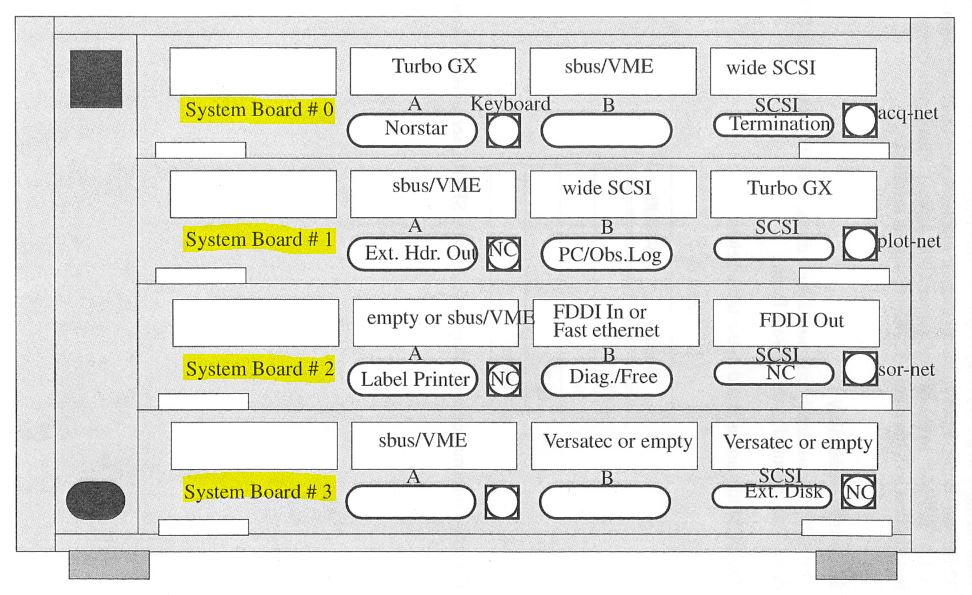 Recording machine -- SBus Interface cards. Fra WG "TRIACQ Installation & Maintenance Manual", p. 2.22 SPARCserver 1000E - boot problem, januar 2021
Tidligere boot problemerSVALEX-2014: 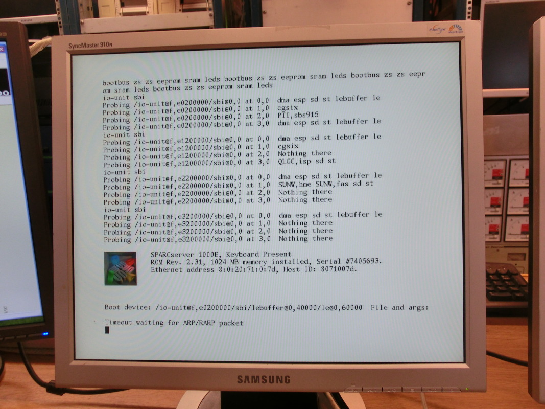 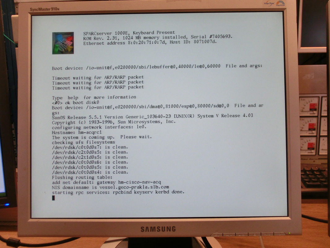 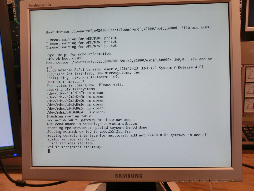  SVALEX-2013: 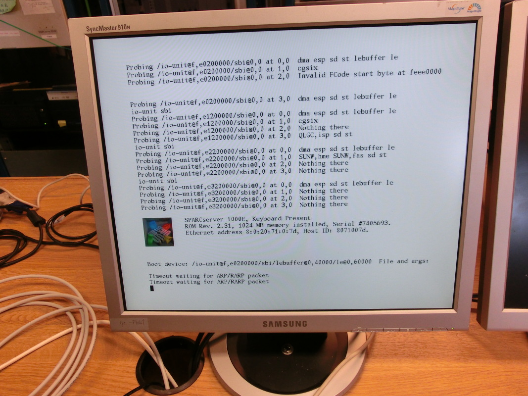 Mulige løsninger
Normal boot prosessSVALEX-2011:  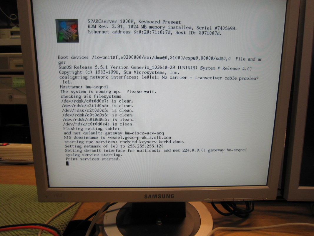 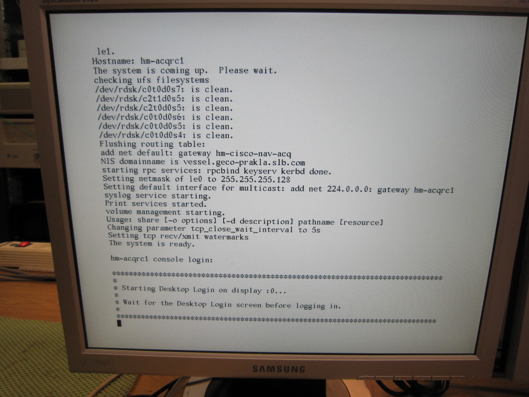 Ext SCSI hard disksExt SCSI DLT Tape Drive
Operativsystem: SunOS Release 5.5.1Components:
Server Bundle additionally includes:
Releases: Initial Release: May 1996 Internet Server Supplement: October 1996
Hardware Update: February 1997
Supported Hardware Platforms:
Newly supported hardware:
Changes from Solaris 2.5:
Streamer Interface (SI) UnitTriAcq Streamer Interface Unit (SI). Klikk for større bilde. TriAcq Spare parts as of Sept. 16, 2002 Parametre på SI/CPU-kort, må settes hver gang SI-enheten startes opp
Recording / Real-time Visualization (RTV) UnitTriAcq Recording and Visualization Unit (RTV). Klikk for større bilde. Enheten består av følgende moduler:
TriAcq Spare parts as of Sept. 16, 2002 Parametre på RTV/CPU-kort, må settes hver gang RTV-enheten startes opp
Under SVALEX-2014 måtte NVRAM på CPU-kortet i RTV'n re-initialiseres, slik:Prosedyre for å re-programmere NVRAM på CPU-kort i RTV-enheten. Klikk for PDF versjon. Streamer Patch PanelN3 streamer Patch Panel. Klikk for større bilde. Streamer Power Control UnitN3 streamer Power Control. Klikk for større bilde. Streamer Power Supply
N3 streamer Power Supply. Klikk for større bilde.
TRIACQ RECORDING PROGRAMMain displayTriAcq recording, hoved display, under produksjon. Klikk for stort bilde. QC displayTriAcq recording, QC display, under produksjon. Klikk for stort bilde.
PROSESSERING AV DATA FRA TRIACQ RECORDING SYSTEMMARIN STREAMER, WESTERN-GECO MODEL: "NESSIE-3" (N3) -- 3 KM
Nessie-3 (N3) main featuresStreamer, N3:
TriAcq system:
N3 oppbyggingA streamer is composed of several different pieces - stretches, active sections, bubbles, repeater bubbles, tail-buoy tow cable. Every second active section is followed by a bubble. Hydrophone groups overlap between sections, hence, at the front of the actives we use a 10m half group section (the last active at the tail has a redundant half group). 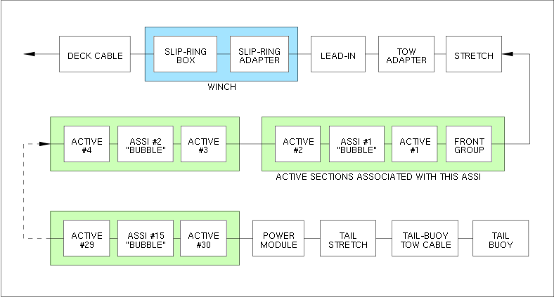 Streamer section nomenclatureAll Western-Geco streamer sections have their own unique identification code and serial number. The code consists of letters, and indicates the function and hardware arrangement of the section. 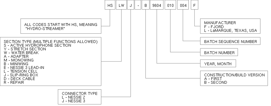 Western-Geco Nessie-3 streamer section nomenclature Konnektor brukt i hver modulKonnektor brukt i hver N3 modul. Klikk for større bilde. Streamer historikk
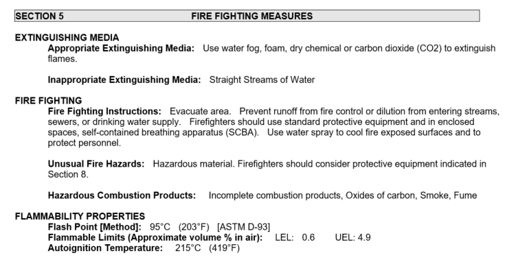
Streamer Oil: ISOPAR M "Safety Data Sheet" EXXON ISOPAR M "Safety Data Sheet":
Link to "Safety Data Sheet"
Source of "Safety Data Sheet":
http://www.msds.exxonmobil.com/IntApps/psims/psims.aspx
"Country Of Use", select: USA
"Product / Trade Name", enter: ISOPAR M
With reference to:
Schlumberger Doc. no.: D20010216
"Operations Manual - Digital Hydrostreamer Nessie 3 & 4"
Issue 9, Dated: March 1997
Section 4.3 "Oil filling - Control of Kerosene"
"The latest skin type with ribs inside (58,5 x 3,5) have a volume of approx. 200 liters (N3-B), [...] and the 50m stretches should be filled with approx 130 liters."
Quantity of ISOPAR-M oil in UiB 3 km streamer:
2 ea Stretch sections (front + tail) ...: 130 liter x 2 ea = 260 liter
30 ea Active sections ...................: 200 liter x 30 ea = 6000 liter
------------------------------------------------------------------------------
Liter in streamer, on winch ......: 6260 liter
------------------------------------------------
Extra: Barrel of oil, for filling-up sections that need it .........: 209 liter
---------
VINSJ FOR N3 STREAMEROversiktWinch UiB for Nessie-3 streamer. Klikk for å åpne album. Ulmatec Baro (formerly Baro Mek. Verksted) has been shown pictures above. Their reply (2014): "We can not confirm the winch was manufactured by Baro. It might look like a Baro winch, but details differ. The hydraulic motor is also unknown to us. It might look like a Geco winch from the 1980'ties. The slip ring unit is similar to the types that Geco used. Baro did not deliver winches to Geco. Odim is a possible supplier. It might also be a copy made in USA or UK."
29 May 2017, measured on winch, in Longyearbyen (storage facility, contact LNS Spitsbergen): Bilder fra SVALEX-2013 fotoalbum:
Krav til hydraulikk / tiloplingerUlmatec Baro AS recommends the following (2014): "When your winch was delivered, the usual hydraulic pressure was 175 Bar. In later years there has been a tendency for increased pressure; nowadays 220-230 Bar is common. Pressure can be reduced in proper hydraulic component ("Trykket kan reduseres i manøverventil ...") in order to use the old winch. Flow rate should be 100-200 liter/minute depending on winch cable force and rotating speed. Hydraulic pump must also be dimensioned according to the number of motors that must be operated simultaneously."
Hydraulikk motor ---- tilkoplinger --- betjeningspanel
SleperingsboksStreamer trinseTrinse for streamer. Brukes også som "spoleapparat" -- trinsen henger i kranwire som styres manuelt fra side til side ved innspoling. Klikk for større bilde.
STREAMER TAIL BUOY
DigiBIRD MOD. 5010 -- DYBDEKONTROLL AV STREAMERIntroduksjonThe streamer is furnished with a set of collars at regular intervals where the vertical control unit (called "Birds") are mounted while the streamer is deployed. We have been using DigiBIRDS mo. 5010 manufactured by ION. Klikk for stort bilde. MERK: Pall og karm er spesielbestilt - de er lengre enn vanlig. Klikk for stort bilde. Data sheets, documentation
Streamer collars
  31 July 2009:
  To: Earl Smith <esmith _at_ oyogeospace.com>:

  PURCHASE ORDER
  --------------
  With reference to quotation (see below) we wish to order:

  --------------------------------------------------------------------------
  Pos  Qty  Unit  P/N             Description
  --------------------------------------------------------------------------
   1   (10)  ea    07-526280-260   Bird collar, standard length, $24.50 each
   2   (10)  ea    07-526281-260   Bird collar, extended length, $29.50 each

  Hi,

  Please quote price and delivery time for:

  10 sets of streamer Bird collars, inner diameter 2.6 inch (both large and small).

  The large collar - 4.4 inch long - has these marks:
        JRC CONCORD TECH, INC   PN 07-526280-260
  The small one - 3.4 inch long - has identical PN:
        07-526280-260
Repair of DigiBIRDS
Programvare for kontroll av DigiBIRDSStreamer Birds programvare. Klikk for større bilde. AIRGUN CONTROLLER - GECO (GETECH) "GUNCO", CA 1990
GUNCO connector wiringThe key to understand the GUNCO connector system is to see how the front slot positions of the MSIBG cards corresponds to the connectors on the rear side - see figure below. We normally only use one MSIBG card located in slot #5. This card will thus have sensors connected on SI3 (labelled "STBD1,2"), and solenoids on SO5 (labelled "STBD 1"). GUNCO connector principle. Click for larger version. GUNCO rack wiring (rear view)Current systemClick to open PDF document: Old systemThe difference is that relays have been added for the airgun solenoid test unit, which allows the operator to monitor sensor voltage and current, and measure resistance to solenoid.
SYNC UNIT - INTERFACE TO EIVA SURVEY COMPUTERThe Sync Unit is placed between the EIVA Survey computer and GUNCO. It receives a trigger command from the survey computer in the form of an ASCII "A" sent over RS232 serial line. The Sync Unit was designed in 1998 and at that time also interfaced two other systems, a magnetometer and a recording system (DFS V) that have both been phased out long time ago. The LCD menu hasn't been updated and thus still provides options that reflects those now unused systems (so don't get confused). At that time the Survey Computer by mistake sometimes issued double shot event triggers a couple of seconds after the proper trigger. This caused the GUNCO to fire when it wasn't supposed to. To prevent this situation the Sync Unit was furnished with a software timer that defined a period in which new triggers were ignored after the first one. The green LED on the front panel is lit during this "trigger ignored" interval. This survey requires 12.5 meter shot point distance, which means the "trigger ignored" setting must be reduced from it's current value of approx 8 seconds, down to 1 second. This is explained in section below.
Routing of CLOSURE and FIRE signal to GUNCOThe GUNCO is now controlled by the "Triacq" recording system of the 3km streamer. Two BNC cables must be relocated so it will become slave to the Sync Unit instead:
Schematics
CPU card inside: "Flashlite-V25"The CPU card is "Flashlite-V25" made by JK Micro. This product has long since been replaced by other versions. The documentation cannot be located (here's a report from someone using it in 2000). But it's quite similar to its replacement, Flashlite 186: How to alter the "trigger ignored" time parameterThe Flashlite 186 CPU card is in reality a tiny MSDOS computer. In initial mode we get contact with the card via serial RS232 cable. A terminal program will then get access to the normal DOS prompt. A user program is automatically started by following instructions found on page 2 of the Flashlite 186 manual: When power is applied to the Flashlite or when it is reset, the board goes through its initialization procedure and then starts DOS. A simple (read-only) AUTOEXEC.BAT file is executed and then the board is ready to use. The batch file performs several functions before the user is given control. The DOS search path is set, the DOS prompt is set, the CTRL-C flag (discussed later in this manual) is checked and finally, an attempt is made to execute a file named STARTUP on the B: drive. This provides a convenient way for custom applications to execute immediately after initialization of the Flashlite. If you wish to have your application start automatically, create a batch file named STARTUP.BAT that invokes the program. Here is the crucial point. The program accepts command line parameters. The first parameter instructs the card to operate in either "OBS" mode (that we use now) or "DFS" mode (which is deprecated). And the second parameter sets the "trigger ignored" duration, in seconds. So in the STARTUP.BAT file the last line will be the program name followed by two parameters, "OBS" and "8" (or close to that figure). The last parameter must be set to "1" instead. If it's omitted the program uses a default value of 15 seconds instead. How can the STARTUP.BAT file be edited? First the program that is running on the CPU card must be terminated or prevented from starting. That can be done in two ways:
The edit process itself is described on page 15 of the Flashlite 186 manual: EDIT.COM EXAMPLE: B:\>edit test.bat FlashLite Line Editor v1.0 Enter h for help New File: test.bat >> i 0: @echo Batch file being processed... 1: mytsr 2: myapp 3: ^Z >> l 0: @echo Batch file being processed... 1: mytsr -> 2: myapp >> q Save before exit (Y,n): y File Saved B:\> Here is a description of the vintage MSDOS EDLIN command line editor.
TRYKKSENSOR FOR SEISMIKK-KOMPRESSORDet er nødvendig å kunne overvåke trykket fra seismikk-kompressor slik at eventuelle luft-lekkasjer på slanger eller i luftkanoner oppdages tidlig. Trykksensor brukt på "Mosby" og "G.O. Sars"
Trykksensor installasjonFF "Håkon Mosby"Air pressure sensor installation on R/V "Håkon Mosby", above instrument room door. HP line on the right. Click to enlarge. FF "G.O. Sars"NOTE: Photo is taken before pressure sensor was installed. It most likely replaces the manometer shown. This is on 2nd deck, near HP outlet and airgun control cables junction box. R/V "G.O. Sars, 2nd deck, near HP outlet and airgun control cables junction box. Click to enlarge. Display for trykksensorBrukt på "Håkon Mosby"
Brukt på "G.O. Sars"
Software for air pressure monitoring and alarmThe sensor display unit is furnished with RS232 (or RS485) interface. A serial command can be sent to the unit and it will respond with measurement value. Python data collection software running on a Linux PC issues sampling commands continuously. When airguns are fired the software extracts the highest pressure value that had been registered lately, in order to plot plot air pressure as function of shot number. The result is shown below. Other process parameters are also sampled. Overvåkning av GUNCO, trykk fra seismikk-kompressor, streamer "Birds", navigasjon DOL (Distance Off Line)Et Linux-basert system som samler inn og presenterer informasjon fra:
All informasjon vises på webside med akustisk alarm hvis egen-definerte alarmgrenser ble overskredet. På denne måten kunne studenter under SVALEX-kursene være alene i instrumentrommet, mens en "usynlig overvåkning" foregikk i parallell. 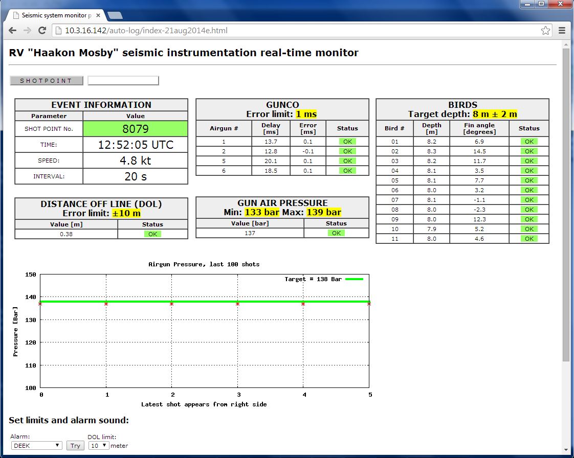 High-pressure piping system on "Kronprins Haakon"
TIDLIGERE TOKT DOKUMENTASJON / FOTOALBUM2014: RV "Håkon Mosby" -- SVALEX-2014 --- siste gang N3 streamer ble bruktKlikk for å åpne SVALEX-2014 fotoalbum. 2013: RV "Håkon Mosby" -- SVALEX-2013Klikk for å åpne SVALEX-2013 fotoalbum. 2011: RV "Håkon Mosby" -- SVALEX-2011Klikk for å åpne SVALEX-2011 fotoalbum. 2010: RV "Håkon Mosby" -- SVALEX-2010Klikk for å åpne SVALEX-2010 fotoalbum. 2010: RV "Håkon Mosby" -- OBS-2010Klikk for å åpne OBS-2010 fotoalbum. 2007: RV "Håkon Mosby" -- SVALEX-2007Klikk for å åpne SVALEX-2007 fotoalbum. 2006: RV "G.O. Sars": Jan Mayen survey, OBS / N3 StreamerKlikk for å åpne OBS/Streamer-2006 fotoalbum. 2005: RV "Håkon Mosby" -- SVALEX-2005Klikk for å åpne SVALEX-2005 fotoalbum. 2004: RV "G.O. Sars: SVALEX 2004Klikk for å åpne SVALEX-2004 fotoalbum. 2003: RV "Polarstern" -- East Greenland SurveyEt komplett system ble sendt til RV "Polarstern" for et seismikk-tokt i 2003. Link til UiB/GEO dokumentasjon (2003)
2002: RV "Håkon Mosby" -- East Greenland Fracture Zone
2001: RV "Håkon Mosby" -- SVALEX-2001http://www.geo.uib.no/eworkshop/gfj294/2001/photos/ HVORDAN BRUKE MODERNE GUNCO PÅ FF "KRONPRINS HAAKON" ...?InnledningVi ønsker å se på muligheten for å bruke moderne GUNCO, som modell "HotShot" fra Teledyne, i stedet for vår Geco GUNCO fra ca 1990 (selv om den er pålitelig). Teledyne, GUNCO modell "Hot ShotDept of Geology/ Univ of Tromsø has acquired airgun controller Teledyne, model "Hot Shot". This unit is able to fire either four Bolt/G-guns or two GI (Generator-Injector) guns. Multiple units (max 4) can be combined, so that in total 16 Bolt/G-guns can be used. Front view, airgun controller unit from Teledyne Real Time Systems - model "Hot Shot". Click to enlarge. Rear view, airgun controller unit from Teledyne Real Time Systems - model "Hot Shot". Click to enlarge. Using MOB (Man over-board) input on the "HotShot" airgun contollerAdvise from manufacturer regarding MOB input on the "HotShot" airgun controller: The man overboard contacts need to be maintained in a closed position for the unit to operate. Once the contacts open the controller will no longer fire. Once closed again it will be able to fire again. So a normally closed pushbutton, with a pull to reset feature is usually what is desired for this. Some users like to have one that is covered as well, so as to not accidentally press it.
Strobe light / flashing beacon - signalling pressurized airguns on deck -- examplesExample: Adeptor.no strobe lights Interface signaler... TriAcq på RV "Polarstern" i 2003 - interface unit brukt den gangenInnledning --- problemet som måtte løsesPå EUROMARGINS-toktet med RV "Polarstern" i 2003 ble det sendt opp et komplett TriAcq recording system og N3 streamer inkl Birds. Skipets GUNCO og Survey Computer ble brukt. Det var dermed et interface problem som måtte løses den gangen. TriAcq systemet forventet ved hvert skuddpunkt et telegram sendt over RS232 serielinje Survey Computer. Telegrammet måtte være av såkalt '''NORSTAR Format 4" type, definert i dette dokumentet: NORSTAR-format4-from-ExtHeader-ver-5-8.pdf (PDF) I tillegg forventet "Streamer Interface" delen av TriAcq en bestemt sekvens av triggesignaler med bestemte polariteter og spenning-/strøm-karakteristikker.
Systemdiagram tegnet av GECO Field Engineer M.G. som deltok under toktet med RV "Polarstern" i 2003. UNDERSØK: Ble TriAcq re-konfigurert på noe vis, for å kunne arbeide med Navigasjonsutstyr og GUNCO på "Polarstern"? Prøv å spore opp M.G. og spør om han husker dette ... "NORSTAR" simulator / interface enhet, for bruk på RV "Polarstern" i 2003
"NORSTAR" er betegnelsen på den spesielle telegrammet som vår normale Survey Computer (brukte software EIVA NaviPac) sender ut ved hvert skuddpunkt. Det er et kompakt binært format med endel snubletråder (bl.a. ENDIAN-hensyn) KretsdiagramLink til flere bilder av enheten under test, og selve hardware'n. Kretsdiagram, "NORSTAR" interface unit. Klikk for stor versjon. Programvare NORSTAR simulatorProgrammet kjørte på MS-DOS ver 6.22 maskin //============================================================================ // // N O R S T A R S i m u l a t o r p r o g r a m // // For RV "POLARSTERN" seismic survey August 2003. // // It is assumed that the interface box labelled "ITEM 20" is // connected to the laptop computer running this program. A 1-to-1 // paralell cable must be used. // // When the program detects signal from Polarstern Gun controller (HIGH TTL // pulse) is sends NORSTAR serial string and CLOSURE IN signal to // Streamer Interface Box. This signal can be simulated by pressing 'T'. // // TRIACQ must be set to start recording after reception of // NORSTAR serial data and CLOSURE IN signal. // // NORSTAR data is time stamped (Year, Julian day, Hour, Minutes // and Seconds) and also event number (shot counter). All other // data fields in the NORSTAR telegram should be disregarded. A valid // checksum is generated. Time and date is read from PC clock. // // Shot number and time stamp is written to screen for each shot. // These values are also logged to file on this computer. // Filename is generated automatically and reflects date and time // the file was created. // // Documentation on this web page: // http://www2.geo.uib.no // // // Rev. Date By Description // ----------------------------------------------- // 0.1 6 Aug 2003 KH/EG/OM Test version // //============================================================================ Fra header i kildekode: NORSTAR.CPP.txt (endre filnavn) C-kompilatorDJGPP - "DJ's GNU Programming Platform" AUTOEXEC.BAT og CONFIG.SYS filer
Kildekode & *.exe program
|
|||||||||||||||||||||||||||||||||||||||||||||||||||||||||||||||||||||||||||||||||||||||||||||||||||||||||||||||||||||||||||||||||||||||||||||||||||||||||||||||||||||||||||||||||||||||||||||||||||||||||||||||||||||||||||||||||||||||||||