|
Surveys and data Instruments
Support to other department sections Support Dr. Scient. thesis Contribution to "Scientific infrastructure"
Obsolete, kept for reference
Last update: April 30, 2025, at 08:49 AM |
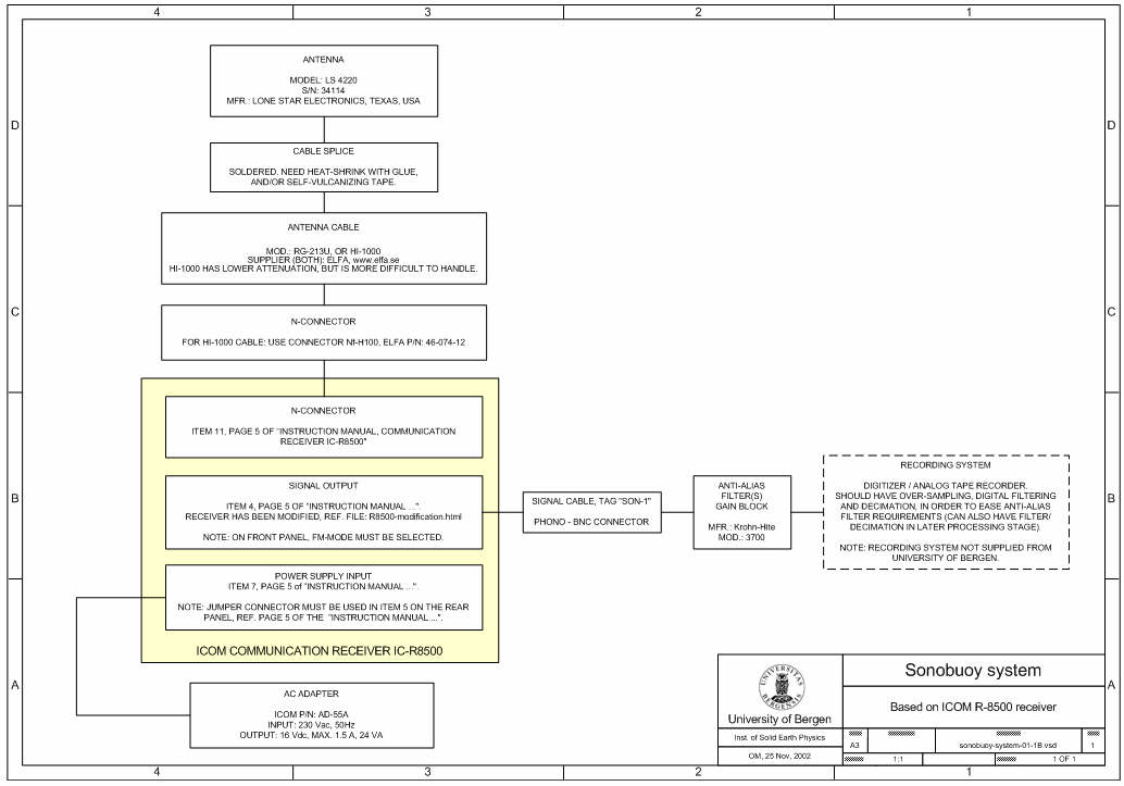
SONOBUOYSTHE SSQ-57A SONOBUOYDepartment of Earth Science uses SSQ-57A types sonobuoys, which are passive, omnidirectional types called LOFAR = Low Frequency Analysis and Recording. Quoting from Military Analysis Network:  The AN/SSQ-57B Low Frequency Analysis and Recording (LOFAR) sonobuoy is an A-size, expendable, non-repairable, calibrated sonobuoy. It uses the AN/SSQ-41B platform, substituting a calibrated hydrophone for frequencies in the 10Hz to 20,000Hz range. The LOFAR sonobuoy provides omnidirectional passive acoustic signature data to the monitoring unit(s). The sonobuoy is calibrated and can be used to accurately measure ambient noise, and through post event analysis, provides Sound Pressure Level (SPL) measurements. SONOBUOY RECEIVER AND RECORDING SYSTEMThe system comprises:
ANTENNA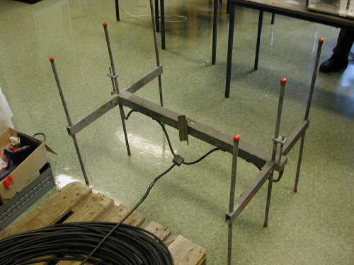
ANTENNA CABLE
RADIO RECEIVERSIcom R-8500
Modified according to this diagram. Icom IC-PCR1500We purchased a sonobuoy radio receiver from Greeneridge Sciences, Inc.. It was a modified Icom IC-PCR1500. WinradioANTI-ALIAS FILTERAn anti-alias filter is needed to remove or reduce input signal frequency components that are above the Nyquist frequency (½ of the sampling frequency). If the A/D-converter has N number of bits, it's dynamic range R is then given by 20*log*2N dB = R dB. From a 'purist' view all frequency components above Nyquist should be attenuated by min. R dB, burying them below the noise floor. The number of decades A between the filter cut-off frequency (-3dB) and the Nyquist frequency is given by: 
where K = filter order (20 * K as a first order filter has 20 dB/decade slope).
The number of decades between two frequencies f1 and f2 is log10(f2/f1). Expressed in terms of Nyquist frequency (½ of sampling frequency fS) and filter cut-off frequency fC we have: 
Rearranging: 
E.g., a 16-bit A/D converter (N = 16), a fourth-order filter (K = 4) and a sampling frequency of 40 kHz (fS = 40000) yields fC = 1363 Hz. The implication is that a large part of the frequency bandwidth (up to ½ * fS ) suffers amplitude attenuation in order to satisfy the need for anti-alias attenuation. The answer to this is oversampling, digital filtering and decimation to final sample rate ... Design of a digital filter: Visit Tony Fisher's Interactive Digital Filter Design web page. USING KROHN-HITE MOD. 3700 AS ANTI-ALIAS FILTERA/D- AND RECORDING SYSTEMSome options:
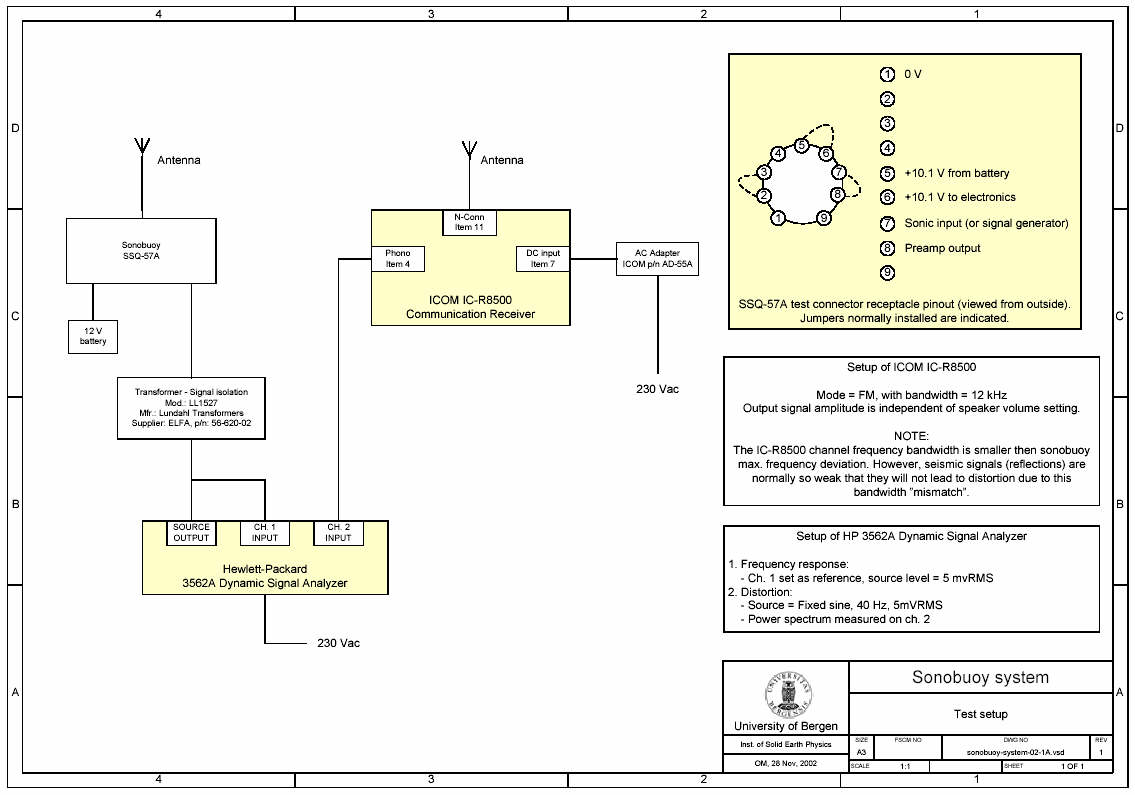
SYSTEM TESTSetupThe following test setup was used: Frequency response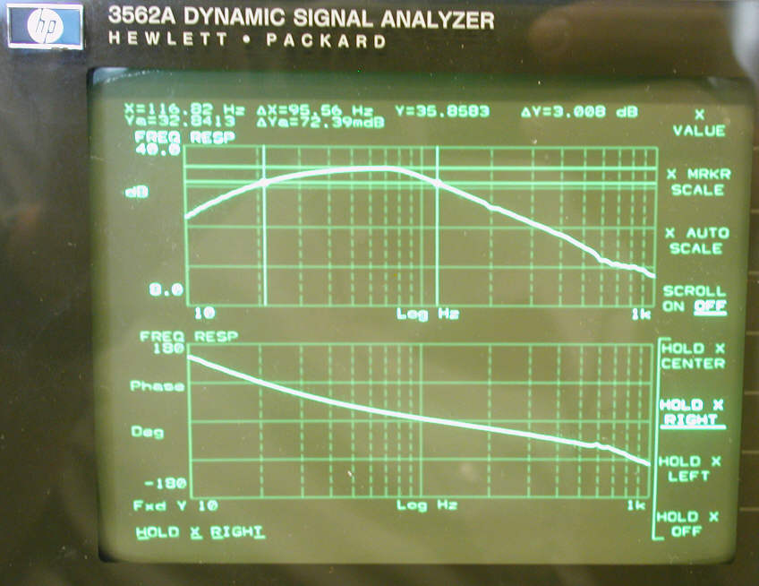
Distortion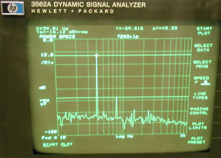
Conclusion: 1st harmonic at 80 Hz is attenuated by 43 dB, harmonics of higher order even more. LINKSManufacturers
TranscriptionMilitary usage
GPS equipped SonobuoysRadio receivers / antenna systems
RF TEST EQUIPMENT
|