
|
Surveys and data Instruments
Support to other department sections Support Dr. Scient. thesis Contribution to "Scientific infrastructure"
Obsolete, kept for reference
Last update: April 30, 2025, at 08:49 AM |
TIME SCHEDULEIMR survey plan is here: http://toktsystem.imr.no/cruises (enter "G.O. Sars" in search field). According to this plan, RV "SARS" will arrive Tromsø 6 June and start our survey the next day.
SEISMIC INSTRUMENTATIONSystem diagramClick to enlarge:
Airgun parameters
 Bolt Technology Airgun model 1900 LLXT, acoustic output at 5 metres depth (source: modified diagram in Specifications for Bolt Model 1900 LLXT LongLifeTM Air Gun'').
8-channel Mini-streamer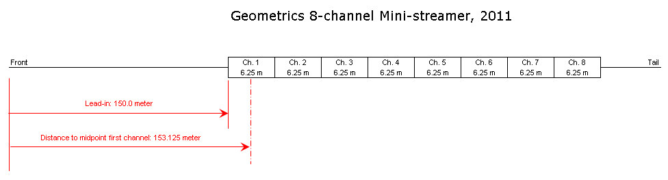
GEODE seismic recording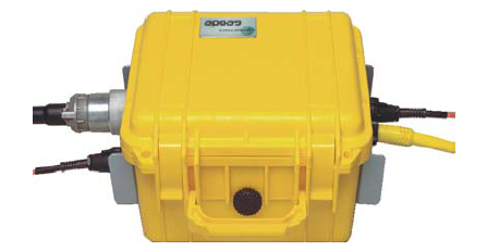
GUNCO connector wiringThe key to understand the GUNCO connector system is to see how the front slot positions of the MSIBG cards corresponds to the connectors on the rear side - see figure below. We normally only use one MSIBG card located in slot #5. This card will thus have sensors connected on SI3 (labelled "STBD1,2"), and solenoids on SO5 (labelled "STBD 1").  GUNCO connector principle.
GUNCO SENSOR CONNECTOR AND PIGTAIL CABLEAs of June 2012, the sensor pigtail connector wiring on G.O. SARS is according to table below. This pigtail is routed to terminals. NOTE: Terminal positions is determined on number of airguns used and their locations on the vessel - there are three junction boxes where the airguns can be connected; one on second deck, adjacent to airgun winch, and two on the third deck, port and starboard side.
GUNCO SOLENOID CONNECTOR AND PIGTAIL CABLE
EIVA SURVEY COMPUTER SIMULATORDuring test it's useful to have two serial datastreams, simulating the Eiva Survey Computer. Here is a Python script that emits two serial RS232 telegrams at regular interval; one consists of the GUNCO trigger command (ASCII "A"), and the other contains Shotpoint number and navigation data. To use the script, first install Python from here: http://www.python.org/ftp/python/2.7.3/python-2.7.3.msi An additional module, called PySerial, must also be installed, in order to use the COM-ports of the PC: http://pyserial.sourceforge.net/ (chose "Download page") The script is here: Eiva-simulator.py Δ Change COM port constants in the beginning of the script, to reflect current COM-ports assignments on your computer. You will find these assignments under Control Panel -> System -> Hardware -> Device manager -> Ports (COM & LPT). Also change sleep(x) instruction withing the eternal "While loop", to obtain desired transmission interval.
GUNCO TRIGGER UNIT - BACKUPThe Eiva Survey Computer emits a serial RS232 character (ASCII "A") to trigger the Gun Controller. An interface unit receives the serial character and triggers the Gun Controller by issuing two closure-type signals in a proper timing sequence. the two signals are called CLOSURE and FIRE. The timing sequence of these two signals is shown below. Gun Controller timing sequence Gun Controller timing diagram. Note: Delay between Closure and Fire leading edge (600 ms shown) is conservative, can probably be reduced to 250 ms (check!) By "closure-type" signals we mean a signal that will short-circuit the input, either by a relay, an opto-coupler or other devices. What is important is that the closure signal provides a method of obtaining galvanic isolation between the two systems. USB-to-serial-TTL interface unitIf we sacrifice the galvanic isolation, we should be able - in an emergency and as a backup - to activate the Gun Controller by means of a simple serial USB-to-TTL interface unit, like the one shown below: 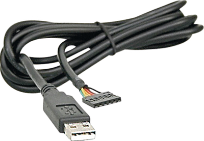 USB-to-serial-TTL interface unit.
USB-to-serial-TTL pinout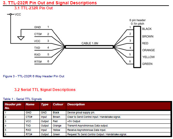 The only way to have control of two output signals is to use TXD and RTS. The signal that appears on the TXD line will of course be a function of the ASCII character that is sent, and the speed setting on the port. If we transmits an ASCII 'NULL' character, we should obtain a clean low-going pulse, with duration determined by this expression: T = 9 * 1/B, where T is duration and B is speed. We multiply by 9 to account for one start bit and the subsequent 8 data bits. BEFORE CONNECTING ANYTHING TO THE GUN CONTROLLER:
Using PySerial to control TXT and RTS signals from interface unitPlease refer to PySerial documentation and examples to see how TXD and RTS signals can be controlled, and how the serial port speed is determined.
RECORDING LOG SHEET
OFFSET DISTANCESNav. reference point is MRU in gravitymeter room. Distance from MRU to SARS stern is 36.6 meter. Two offset distances are needed:
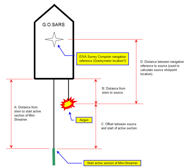 Offset distances.
GUNCO SENSOR DISPLAYThis is what a GUNCO sensor display could look like. Click to see larger version. NOTE: Airgun no. 1,2 and 6 is OK. No. 5 has crossfeed from the solenoid pulse; the "crosfree blanking" feature of the GUNCO is activated (red area), causing any signal that appears within the read zones to be ignored.  GUNCO sensor display. Click to enlarge.
PROBLEMS .....Mini-streamer26 June 2012: Four last channels of mini-streamer look weird. The display gain, which is indicated below the channel number, is much larger for the four last channels. 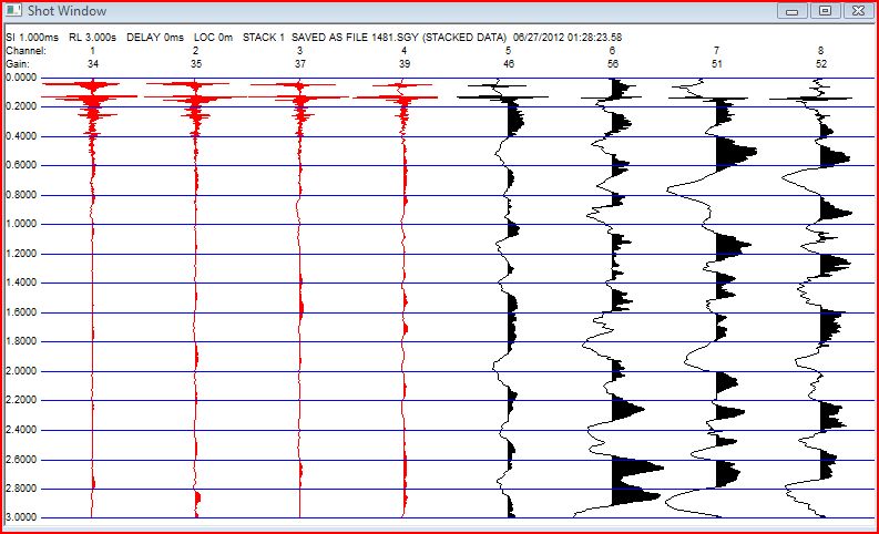 Recommended action:
|
|||||||||||||||||||||||||||||||||||||||||||||||||||||||||||||||||||||||||||||||||||||||||||||||||||||||||||||||||||||||||||||||||||||


