
|
Surveys and data Instruments
Support to other department sections Support Dr. Scient. thesis Contribution to "Scientific infrastructure"
Obsolete, kept for reference
Last update: April 30, 2025, at 08:49 AM |
 OBS-2014 photo album. Click to open. NAV DATAOverview of time stamping system UiB OBS-2014 survey: Overview of time stamping hardware and software. The Survey Computer is the master of the system. All parameters for the seismic line - start and end positions, interval between shot points are entered by the operator. When the line is activated, the survey computer takes care of the rest by issuing the necessary triggering signals to other units in the system, and generating proper log files. Processed nav data is delivered in modified UKOOOA P1/90 format. Download the P1/90 specifications from here. In the P1/90 file, the parameters associated with a shot point is put in a single line of text, however the formatting is very compact making the identification of the individual parameters a bit difficult. GEOMAR has established an unofficial extension of the standard to accommodate the time stamp information that OBS surveys require. These time stamps are put in record positions that are normally assigned for other purposes, but can be "sacrificed" if need be. See more detailed explanation below. UTM Zone, reference point on vesselAll UTM data are relative to UTM Zone 35. All coordinates are also relative to the position of the gravity meter on board the ship.  Gravitymeter is placed at frame 40. Frame distance is 0.6 m. Thus, gravity meter is 40 x 0.6 m = 24.0 m from the stern. Acquisition geometryAirgun offset distanceAirguns are positioned 43 meters behind the stern. We have to add offset between gravity meter and stern, to obtain the total offset between source and positions given in navdata files. Thus, total offset between source and positions given in nav data files is: 43 m + 24.0 m = 67 m. UKOOA P1/90 navdata formatOutput from nav data processing should be in UKOOA P1/90 format, slightly modified to accommodate three decimals in time value. The UKOOA P1/90 format specification can be downloaded from SEG. It's a fixed-position format without any <SPACE> or <TAB> delimiters between fields, so it can be hard to read. However, by inserting appropriate comment field in the header, it can be made much more legible, as this example shows. The first part is the header; the individual shot points are at the end (six lines) : H0100 SURVEY AREA ISFJORDEN, SVALBARD H0101 SURVEY DETAILS SVALEX-2005 H0102 VESSEL DETAILS R.V. HAAKON MOSBY H0104 STREAMER DETAILS 240 CH GECO NESSIE-3 H0200 SURVEY DATE AUGUST - SEPTEMBER 2005 H0201 FILE CREATED 16-Jan-2006 H0202 FILE VERSION UKOOA P1/1990 H0300 CLIENT SVALEX-2005 H0400 GEOPHYSICAL CONTRACTOR UNIVERSITY OF BERGEN, NORWAY H0500 POSITIONING CONTRACTOR N/A H0600 POSITIONING PROCESSING O.M. UNIVERSITY OF BERGEN, DEPT OF EARTH SCIENCE H0700 POSITIONING SYSTEM H0700 SURVEY COMPUTER SOFTWARE NAVIPAC, EIVA, DENMARK H0700 H0800 SHOTPOINT POSITION CENTRE OF SOURCE H1000 CLOCK TIME UTC H0900 OFFSET SHIP SYSTEM TO SP 70.0 M BEHIND H1200 SPHEROID AS SURVEYED A,1/F WGS-84 Spheroid 6378137.000 298.2572236 H1300 SPHEROID AS PLOTTED A,1/F WGS-84 Spheroid 6378137.000 298.2572236 H1400 GEODETIC DATUM AS SURVEYED WGS-84 H1500 GEODETIC DATUM AS PLOTTED WGS-84 H1700 VERTICAL DATUM SL : ECHO SOUNDER H1800 PROJECTION 001 UTM NORTHERN HEMISPHERE H1900 ZONE 33X NORTHERN HEMISPHERE H2000 GRID UNIT 1 METRE H2001 HEIGHT UNIT 1 METRE H2002 ANGULAR UNITS 1 DEGREES H2200 CENTRAL MERIDIAN 15 DEG E H2600 H2600 00011111111112222222222333333333344444444445555555555666666666677777777778 H2600 78901234567890123456789012345678901234567890123456789012345678901234567890 H2600 -NAME-><->---<-SP-><---LAT--><--LONG---><--EAST-><-NORTH-><-DEP><D><TIME>- SLine34-05 18781022.23N 141348.31E 482384.58677774.7 215.8242180734 SLine34-05 19781023.47N 141353.32E 482416.98677812.8 214.7242180755 SLine34-05 20781024.73N 141358.24E 482448.78677851.4 212.3242180816 SLine34-05 21781026.00N 1414 3.08E 482480.08677890.4 209.6242180837 SLine34-05 22781027.28N 1414 7.88E 482510.98677929.7 207.6242180858 SLine34-05 23781028.53N 141412.83E 482543.08677968.1 206.2242180919 UKOOA P1-90 navdata format structure. The shot point (SP) parameter, for instance, is located from column 20 to 25, as shown below. The two column numbering lines, together with the parameter name line, is an aid in determining the column position of the different parameters. These three "legend" lines are not common - they are only inserted by the software we use to generate UKOOA P1/90 files. +--------> Column 20 | | +---> Colomn 25 | | 222222 012345 <-SP-> 18 19 20 21 22 23 Updated standard: P1/11The P1/90 standard was updated some years ago:
We have not evaluated the new standard yet. "OBS" modification of UKOOA P1/90 navdata formatOBS refraction surveys means that source (airguns on ship) and receivers (OBS placed on the bottom, or on land, as an extension of the profile) must maintain a common, accurate - to the nearest millisecond - time base. This is accomplished by special oven-controlled oscillators in the OBS instruments, and GPS locked clocks in land based instruments. On board the ship, the exact time of the shot point is recorded by two time-tagging systems operating in parallel (details provided in table of geophysical equipment above). The time field in the UKOOA P1/90 format only accommodates seconds without decimals. The format has been modified to permit storage of shot times with six decimal places, of which only the three most significant decimals are used. An example of modified file: H2600 FILE FORMAT MODIFIED TO INCLUDE SHOTPOINT TIME IN COLUMNS [7..19] H2600 H2600 00011111111112222222222333333333344444444445555555555666666666677777777778 H2600 78901234567890123456789012345678901234567890123456789012345678901234567890 H2600 <--SP TIME--><-SP-><---LAT--><--LONG---><--EAST-><-NORTH-><-DEP><D><TIME>- SSM-1 101921.956000 99632728.92N 74033.97E 732982.37045135.6 171.3297101921 SSM-1 102109.690000 100632728.28N 74019.50E 732783.87045101.1 172.4297102109 SSM-1 102251.455000 101632728.66N 740 5.07E 732583.57045098.3 176.4297102251 "EIVA" Survey Computer shot event log filesThe format of these shot point log files is as follows: Event Date Time Easting Northing St.d. Gyro Dal Dol Kp Object Data ----------------------------------------------------------------------------------------------------------- 000057 2010.06.02 02:51:41.914 0334654.77 07118140.71 00.90 038.1 00000.15 005.14 000.000 "H Mosby f " 3002.22 9449.08 52045.27 "" 01 000058 2010.06.02 02:52:59.662 0334792.73 07118285.63 00.80 037.7 00200.24 005.27 000.200 "H Mosby f " 3010.88 9448.82 52040.90 "" 01 000059 2010.06.02 02:54:19.285 0334928.16 07118432.47 00.80 037.6 00399.98 002.25 000.400 "H Mosby f " 3019.18 9449.93 52035.06 "" 01 000060 2010.06.02 02:55:36.205 0335067.61 07118575.91 00.70 037.9 00600.02 004.48 000.600 "H Mosby f " 3027.67 9451.44 52025.12 "" 01 Parameters are given in first line. Most are self-explanatory, except these:
The last item in each line ("" 01) can be ignored. Shot time stamp filesThe airgun controller (GUNCO) provides a signal that indicates when the shot was fired. Technically, it's a TTL-level signal, normally in a HIGH state (approx 5 Volt); a short pulse of approx 100ms duration will be emitted at every shot, with the falling edge indicating the nominal shot point. Yes, individual air guns may fire a certain amount of time before or after this nominal shot point, but if this deviation is too large - in our case +/- 2 ms off target - the GUNCO will provide av audio and visible warning that the shot should be discarded. The signal is routed to a special GPS receiver (Ashtech model ProFlex Lite DG14) furnished with a trigger input line. The trigger can be specified at falling or trailing edge of a pulse. When a trigger occurs the units transmits a record of the time stamps on one of its serial ports. Time stamp values are NOT provided in UTC format, but in the format that is used internally by the GPS system - so called "GPS time". The difference is that "leap seconds" are inserted at irregular intervals into the UTC timing in order to keep UTC in sync with Earth's rotation (which is gradually slowing down, but not in a linear fashion), whereas GPS time is based on atomic oscillations that are unaltered over time. As of July 2014, GPS is ahead of UTC by 16 seconds (citation needed). $PASHR,TTT,1,01:34:50.6736354*0A $PASHR,TTT,1,01:35:04.7150736*0D $PASHR,TTT,1,01:35:34.7395346*06 $PASHR,TTT,1,01:36:04.7639513*03 $PASHR,TTT,1,01:36:34.7883658*03 $PASHR,TTT,1,01:37:04.8127920*09 Parameters are comma delimited. Record structure mimics NMEA GPS telegram format. Using first line as example, parameters are:
Ashtech time stamp unit "ProFlex Lite DG14"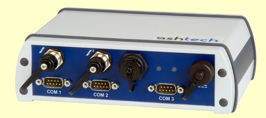 User's ManualCOM port pin out Ashtech DG14 COM port pin out, from page 13 in manual. Unit configurationCheck options installed by issuing the $PASHQ,RIO command, ref.page 15 in the manual. Here is the response: $PASHR,RIO,DG16,DD04,,TOPUB_LE_C__YXDR___I,71168612DG6201222026*17 Old Ashtech GG24 config; Setup for Ashtech GG24 : =========================== ; ; Reset with default settings $PASHS,RST ; ; Set receiver in mixed GPS/GLONASS mode $PASHS,SYS,MIX ; ; Set elevation mask to 10 degrees $PASHS,PEM,10 ; ; Send NMEA message GGA on port C $PASHS,NME,GGA,C,ON ; ; Send NMEA message SAT on port C $PASHS,NME,SAT,C.ON ; ; Send NMEA message ZDA on port C $PASHS,NME,ZDA,C,ON ; ; Set NMEA "send message interval" to 1 Hz $PASHS,NME,PER,1.0 ; ; Set event marker signal to falling edge $PASHS,PHE,F ; ; Set 1PPS trigger edge to falling edge $PASHS,PPS,01.00,+000.0000,F ; ; Output Event marker message on port C $PASHS,NME,TTT,C,ON ; ; Output Signal-to-Noise-Ratio (SNR) in dB*Hz $PASHS,SNR,DBH ; ; Output Event marker time in GPS-system-time $PASHS,TSC,GPS ; ; Save settings in battery backed-up memory $PASHS,SAV,Y
SoftwareAll scripts are written in Python version 2.7. Download Python interpreter version 2.7 from here. Generating UKOOA P1/90 file
   DESCRIPTION:
   Merges information from two sources: a) The navigation files from the EIVA Survey
   computer, which holds records of Shot point (SP) number, UTM coordinates, date,
   time, depth and other parameters and b) accurate GPS based timing of each shot.

   Sequence of processing steps:

   A] The script applies an offset to EASTING & NORTHING coordinates in EIVA navigation
      file, in order to adjust for distance between seismic source and position reference
      point. Offset adjustment it based on treating shot points as vectors: First the
      difference vector between current and previous SP is calculated. This vector is
      divided by its own length, obtaining a unit length vector. The unit length vector
      is then multiplied by the offset distance, yielding a correction vector that is
      subtracted from current SP. First SP is treated differently though, as there is no
      previous SP in that case; instead, next SP is used to obtain correction vector.
      Idea for improvement: Use Python libs "SciPy" and "Numpy" and perform interpolation as in this example.
   B] Collect corresponding GPS time stamp from the other file. Convert GPS time stamp to
      UTC. Check that timestamps in EIVA and GPS-file differs only by a user-defined
      amount.
   C] Generate UKOOA file.

   INPUT FILES:
    Must be in same directory as this script. Name of input files stated in Constant
    section.

   OUTPUT FILE:
    Will be placed in same directory as this script.

   UKOOA P1/90 HEADER, UTM ZONE, OFFSET DISTANCE:
    See 'Constant' section.

   EXTERNAL LIBRARY USED:
    UTM to Lat/Long conversion - download library from:
       http://www.pygps.org/#LatLongUTMconversion  (no, link seems to be dead).
        LatLongUTMconversion.py download from local repository.
        Should be replaced by pyproj module when time permits.
    Either:
    a) On Linux: Unpack it, and run "python setup.py install" as root.
       In order to build Python modules you must first install 'python-devel'.
    b) Windows/Linux: Put "LatLongUTMconversion.py" in the same directory as this file.
DATAProfiles
GRAVITY METER BASE READINGSLand gravimeter calibration table Calibration table land gravimeter L&R S/N: G-936. Click to enlarge. Converting the counter reading to milliGalsExcerpt from p.1-9 of G-936 Instruction Manual:
  If the counter reading is 2654.32, look at the calibration table for your meter. Remember that each meter has its own unique table.

                          Portion of calibration table
     _____________________________________________________________________________
    /                                                                             \
   /    Counter reading           Interval factor           Cumulative value       \

            2500   ..............     1.00794    .............   2519.42
    +---->  2600   ..............     1.00799    .............   2620.21  <---+
    |       2700   ..............     1.00805    .............   2721.01      |
    |       2800   ..............     1.00811    .............   2821.82      |
    |                                                                         |
    |    Divide the reading into two parts:                                   |
    |                                                                         |
    +---->  2600.00                               2620.21  <------------------+
            + 54.32                                +54.75  <----+
            -------                               -------       |
            2654.32                               2674.96       |
                                                                |
         Interval factor x reading within interval              |
                                                                |
                               1.00799 x 54.32 = 54.75  <-------+
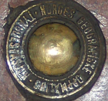
Tromsø reference location
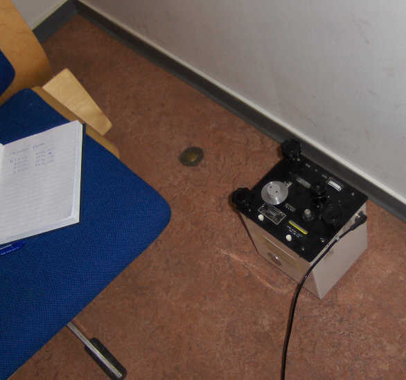
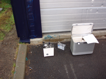
Base reading Tromsø 20 July 2014 RV Håkon Mosby, Tromsø 20 July 2014, gravity base reading. Click to enlarge. Mosby location [insert map/photos]: A) MARINE GRAVITY METER STILL READING:
..................................
DoY Time_UTC Digital_gravity Spring_tension Cross_coupling Raw Total_correction
------------------------------------------------------------------------------------------------
201:08:55:40 6159,8 6159,8 0.0 -7.0 -0.1
201:10:27:20 6159.8 6159.8 0.0 -6.0 -0.2
B) MEASUREMENTS ON QUAY BESIDE SHIP ( 1st time)
.............................................
i. Distance from jetty to water surface: 3.2 meter
ii. Land gravimeter:
10:40 UTC: 6018.160
6018.160
6018.160
6018.155
C) MEASUREMENTS ON TROMSØ REFERENCE POINT S (SEE ABOVE)
....................................................
Land gravimeter:
11:02 UTC: 6017.875
6017.878
6017.875
D) MEASUREMENTS ON QUAY BESIDE SHIP (2nd time)
...........................................
i. Distance from jetty to water surface: 3.26 meter
ii. Land gravimeter:
11:20 UTC: 6018.190
6018.165
6018.185
6018.190
6018.185
E) MARINE GRAVITY METER STILL READING:
..................................
DoY Time_UTC Digital_gravity Spring_tension Cross_coupling Raw Total_correction
------------------------------------------------------------------------------------------------
201:11:32:30 6159,7 6159,8 0.0 -2.0 0.0
F) SYNCHRONIZATION OF SPRING TENSION VALUE
.......................................
Due to circumstances the synchronization of spring tension value in software, and value shown on sensor
counter, was done after base reading. This is not critical - it is only a question of offset adjustment.
New synchronized reading: 14232.2. Offset adjustment of spring tension value: (14232.2-6159.8) = 8072,4
Base reading Longyearbyen 12 August 2014Mosby location: Bykaia A) MARINE GRAVITY METER STILL READING:
..................................
DoY Time_UTC Digital_gravity Spring_tension Cross_coupling Raw Total_correction
------------------------------------------------------------------------------------------------
224:18:21:00 14641.9 14641.9 0.0 20 0.1
B) MEASUREMENTS ON QUAY BESIDE SHIP ( 1st time)
.............................................
i. Distance from jetty to water surface: 3.9 meter
ii. Land gravimeter:
18:37 UTC: 6421.890
6421.890
6421.890
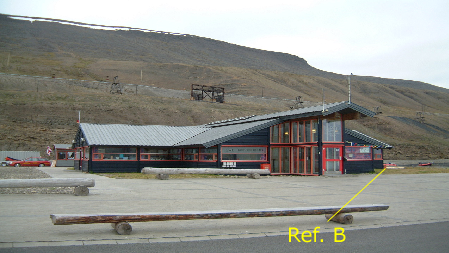
C) MEASUREMENTS ON LONGYEARBYEN "REFERENCE POINT", HARBOR OFFICE
..............................................................
Land gravimeter:
18:53 UTC: 6422.273
6422.273
6422.273
D) MEASUREMENTS ON QUAY BESIDE SHIP (2nd time)
...........................................
i. Land gravimeter:
19:04 UTC: 6421.940
6421.940
6421.940
The difference between reading B and D is (6421.940 - 6421.890) = 0.05 counts (approx 50 uGals). Check land gravity meter later on stable surfaces to see if this is a instrument related issue.
E) MARINE GRAVITY METER STILL READING:
..................................
DoY Time_UTC Digital_gravity Spring_tension Cross_coupling Raw Total_correction
------------------------------------------------------------------------------------------------
224:19:18:50 14642.0 14641.9 0.0 6 0.5
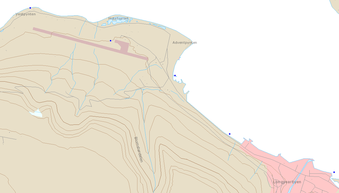
Gravity station, Longyearbyen Airport (now destroyed)The old reference points at Longyearbyen Airport were been destroyed when new terminal building was constructed in 2007. So in 2008 we established our own "secondary" reference points, one near the Harbor Office at Bykaia, and the other near Bringkaia, by taking the approximate difference between that old point, and the new secondary points. Several difference readings have been performed in order to establish an accurate difference, see table below. Here is information about the old gravity stations at the airport.
Secondary "reference point" at Harbor Office, Longyearbyen
Coordinates
Difference between old and new (secondary) reference point
CARGO MANIFESTTing som skal lastes på MOSBY før avgang 7. juli: Utstyr som må testes før pakking POS BESKRIVELSE
-----------------------------------------------------------------------
1 Streamer BIRD utstyr:
1.1 Palle med Streamer Birds
1.2 Birds vinger og verktøykasse i Alukasse
1.3 Bird Lithium batterier (som festes utenførs på brovingen) i liten ALUkasse
2 Streamer "bubbles" i ALUkasse
3 Tidsstempling av shot-points: Plastkasse med GPS + antenner (inklusiv reservesystem)
4 Magnetometer: Plastkasse med reservedeler og manual
5 Gravimeter palle (gravimeteret ble ikke montert 20. juni da leider var vekke og maskinrommet blokkert pga maskinoverhaling).
6 Verktøykoffert
7 TRIACK streamer recording system
7.1 Reservekort til Triacq system (2 stk svarte plastkasser)
7.2 Tape media 30 stk + RENSETAPE
7.3 Tastatur/mus/ + plate til Sun maskin
7.4 Reserve switch og andre deler
7.5 Manual, også til QC system
8 GUNCO reservedeler, liten ALUkasse (NB det står også en reserve GUNCO i skap ved dør inn til Instrumentrom).
9 Mini-streamer recording: Plastkasse med GEODE + recording laptop. Låne reserve GEODE fra W.W. (har sendt email)
Utstyr som hentes direkte fra lager på Laksevåg1 Magnetometer, hvit transportkasse 2 Mini-stramer i oransje plastkasse 3 Dekk-kabel streamer (med reserve??) 4 Magnetometer Winch (som ble reparert v/Karmøy Winch) NYE PALLEKARMER TIL BIRDSFirma som lager paller og karmer etter mål:
PHOTOS |
|||||||||||||||||||||||||||||||||||||||||||||||||||||||||||||||||||||||||||||||||||||||||||||||||||||||||||||


